
 BUY NOW
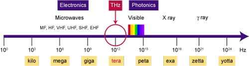
Introduction: The THz Gap and the Need for Cost-Effective Infrared Detection
Traditionally, long-wave infrared detectors have been costly, gallium arsenide- or indium phosphide-based detectors found in night vision cameras. While cheaper and easier to produce in volume, CMOS technology suffered from the so-called ‘THz gap’ or ‘far-infrared gap’ of the electromagnetic spectrum, unable to detect these long wavelengths. Today, an intriguing solution is becoming available in the form of a THz range CMOS detector for cost-effective, long-wave infrared detection. This new THz CMOS technology has limitless potential in various applications, from early-cancer detection to more cost-effective night vision, cheap enough to come equipped on all cellphones. It can even be used in public areas such as airports to detect viral infections, for example, where fever is a symptom.
Background: UTD’s Groundbreaking CMOS Technology for Infrared Detection
![]() In 2022, Behnam Pouya and a team of scientists at the Texas Analog Center of Excellence (TxACE) located at the University of Texas at Dallas (UTD), led by Dr. Kenneth K. O, embarked on a project. This project, on which Behnam based his Ph.D. dissertation, set an unprecedented milestone in the realm of infrared detection by bridging the THz gap and bringing to the photonics community a CMOS technology diode-based detector in the long-wave infrared spectrum. Indeed, it appears difficult and costly today to get laser sources or detectors compatible with this long wavelength range.
In 2022, Behnam Pouya and a team of scientists at the Texas Analog Center of Excellence (TxACE) located at the University of Texas at Dallas (UTD), led by Dr. Kenneth K. O, embarked on a project. This project, on which Behnam based his Ph.D. dissertation, set an unprecedented milestone in the realm of infrared detection by bridging the THz gap and bringing to the photonics community a CMOS technology diode-based detector in the long-wave infrared spectrum. Indeed, it appears difficult and costly today to get laser sources or detectors compatible with this long wavelength range.
To fill this void, UTD’s research team created a 20-THz CMOS detector (≈ 15µm wavelength). However, the team needed the right transmitter source to characterize their detector, and in the electrical domain, the highest-frequency transmitters available are limited to approximately 2 THz. Therefore, the team searched for an optical source suitable for the detector characterization.
Problems and Setbacks: Challenges in Characterizing the THz CMOS Detector
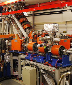
Initially, Behnam’s team utilized a free-electron laser (FEL) from a German university to characterize their previously developed 10 THz CMOS detector. The problem was that they had to fly to Germany to access this device, which was not feasible for time and budget. Gaining access to an available free-electron laser in the United States can be difficult, and desiring an in-house solution, Behnam’s team turned to a laser manufacturer based in Switzerland, which possessed a 20 THz pulsed laser. This potential solution fell through when they realized that the laser could not provide the output power needed, and the pulsed nature of the output was less practical than a continuous-wave (CW) output laser would be for their purposes.
Another possible solution was to utilize a blackbody radiation source, as these devices provide the 20 THz emission required. However, despite being the traditional, time-tested method for IR calibration, the team identified a few major problems to overcome.
The first problem was that the blackbody source did not provide a sufficiently high output power (<1 mW), which was further compounded by some other unfortunate characteristics of the blackbody. The output wave from this device is highly broadband (≈ 0.5 µm – 100µm), not fixed to one wavelength. Given that a bandpass filter in this 20 THz range is hard or impossible to come by, they had to use both a low pass and high pass filter to create a bandpass around 15µm. The next problem was a lack of polarization from the blackbody, which required them to add a polarizer to the setup. Furthermore, the radiation is not collimated, requiring multiple lenses to focus the output onto the sample. Adding filters, lenses, and a polarizer increased the complexity of their setup and, more importantly, caused a significant loss of the already minuscule power level with which they started.
Finally, they discovered that it took work to control the output power of a blackbody. It is not a linear process; it requires setting a temperature and waiting fifteen minutes for it to settle. If the power differs from where you want it, you must repeat that process. And, just for ‘icing on the cake,’ the team had to send the blackbody device back to the manufacturer every ≈ 100 – 200 hours to replace the filaments.
The Solution: Quantum Cascade Lasers
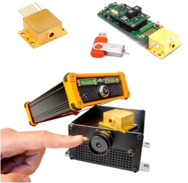
Blackbody sources are wonderfully helpful and robust devices, but for this unique application, there must be a better tool for the job. So, what now? Behnam set out to find a quantum cascade laser (QCL) with a 15 µm wavelength and enough power to handle the characterization. The QCL he found was manufactured by the French company mirSense (the only company offering QCLs up to 17µ), whose products are distributed in the U.S. by RPMC Lasers. Working with a U.S. distributor like RPMC was beneficial for the UTD team since they did not need to worry about import and customs paperwork (one of the many benefits provided by RPMC).
Simplifying the Setup: How a Quantum Cascade Laser Made Infrared Detection Easier
Behnam needed a user-friendly laser, as he works in an electronics lab, not an optical lab equipped with the necessary components for complex setups. He wanted to avoid some of the previous issues, maintaining a simple system for their tests, and as it turned out, the QCL from mirSense was very easy to use.
Since this QCL is already collimated, he needed only one lens to focus the output beam onto the detector. He used a pyroelectric detector to measure the beam waist area and the incident power level. Then, he replaced the pyroelectric version with their 20 THz CMOS detector to check the responsivity and compare the output voltage with the original measurements. The CMOS device was mounted to a 3-axis translation stage, with the Y-axis fixed, scanning in the X and Z axes to take a photo of the incident beam.
Optimizing Performance: Thermal Management for Quantum Cascade Lasers
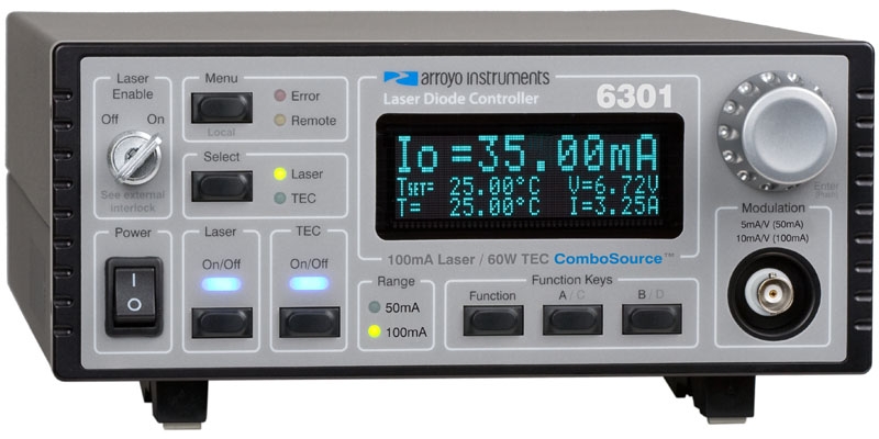
While Behnam and his team found the QCL and its GUI software easy to use and integrate with LabView to control laser temperature, there were still a few minor hurdles to overcome. The QCL should operate below 0^oC, so it was mounted to an active heatsink (Arroyo 285) with a 5A temperature controller. They chose a diode driver/controller combo (Arroyo 6340-QCL) that drives the laser and controls the TEC inside the QCL housing. They set the laser temperature to ≈ -10^oC and the heatsink to just below 0^oC. However, this resulted in much condensation on the laser and heatsink. So, Benham contacted mirSense, who advised them to set the heatsink to a few degrees above 0 (≈ 8^oC), which fixed all the condensation issues. This point highlights another benefit of working with RPMC and their trusted partners, as they are always willing and able to provide quick and knowledgeable assistance well after the delivery of the product.
The last minor problem they faced also involved the heatsink since it was air-cooled rather than water- or even nitrogen-cooled. Due to limitations on the heatsink, it could not sufficiently remove the waste heat buildup from the QCL, causing a rapid heat increase when operating above 900mA of injection current and falling short of the 19 mW CW maximum output specification. This heatsink issue is often a problem in the laser community when developing a new technology or process. Sometimes you crank up the drive current until you max out the heatsink and realize you need something a bit more robust.
Unexpected Benefit: Proving Electronic Detection, Determining Detector Threshold & Sensitivity
The good news here; this heatsink issue ended up being acceptable, as the team found it advantageous to operate the laser below maximum power for their characterization. Discussing this project with the community, Behnam was faced multiple times with a similar question: “Are you sure this is detecting an electronic signal and not being affected by temperature changes?” Characterizing an electronic detector is not the same as a pyroelectric or optical detector. In these thermal detectors, you measure power based on temperature, but with an electronic detector, you collect the electronic wave signal rather than the conversion to thermal energy.
Based on a CMOS integrated circuit, this new detector utilizes a diode to detect the incident electronic wave. Heating this diode in any way, whether from the electronic wave of interest or any other source, will change the output voltage and skew the measurement. Therefore, operating the laser at a lower output power, mitigating any thermal effect, can prove that electronic detection is dominant rather than any thermal effect. So, Behnam reduced the output power to perform the critical characterization without any thermal influence. Then, he continuously dialed down the output power to find the detection threshold and determine the sensitivity of his detector.
Cost-Effective and Scalable: The UTD Team’s Success in IR Detection Changes the Landscape
The team’s characterization was very successful, leading to the development of the highest frequency detection in the world, all based on a much more cost-effective and easily integrated CMOS technology. Regarding traditional night vision technology, for example, cheaper gallium arsenide or indium phosphide-based systems can still easily cost $500 – $1,000. Gallium arsenide requires extensive post-fabrication processing, making it difficult and costly to produce, while CMOS technology can be produced quickly and efficiently in large volumes. When fully developed and ready to hit the market, these CMOS-based devices could drastically reduce the price of a night vision capable component to a range of ≈ $10 – $20 with mass production, making it feasible for all cellphones to come equipped with this ability at a minimal cost. This reduction of cost and technical difficulty would also apply to any other application.
RPMC Lasers is the leading OEM laser supplier in the US, focused on providing diode lasers, CW and pulsed lasers, laser amplifiers, and laser accessories to the industrial, medical, life science, and defense markets. Our technical staff has a vast understanding of lasers, the laser industry, and hands-on experience, making them a valuable resource in selecting the best laser for an application, whether a standard laser or a custom solution. Contact Us with the button below or email us at [email protected]!