
 BUY NOW
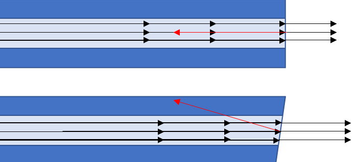
When you look through a window at night and see your reflection, that is because on average 4% of the incident light is reflected at the interface between air and glass. While 4% may seem like a small amount when dealing with lasers, a 4% back reflection can have more than enough power to destabilize or even permanently destroy the laser. If the laser beam is perfectly aligned through the system, so too will the back reflections be perfectly aligned to go back into the laser cavity.
While back reflections are definitely problematic for lasers in general, they are most problematic for single-mode lasers. Especially single-mode diode lasers. There are two primary reasons for this extreme sensitivity. As we discussed in our previous blog post titled “Laser Diode Fundamentals: Single Longitudinal Mode Diodes,” injection seeding can change the gain threshold of a laser. In that blog, we explained that by controlling the feedback into the laser you could select specific longitudinal modes. Similarly, when unwanted back reflections exist in the system, it will change the gain threshold in unintended ways and cause the longitudinal mode structure to destabilize.
Additionally, when we are looking at single-mode laser diodes, there is an even more significant risk. A typical single-mode laser diode has an active area of approximately 1 x 3 micron. These single-mode lasers tend to be much lower power than multimode lasers, and the energy density is exponentially higher. As a result, a back reflection of as little as 4% is often more than enough to overheat the laser facet resulting in catastrophic optical damage (COD).
One approach to solving this issue is to make sure that any window or lens is anti-reflection (AR) coated. A second less expensive method for reducing back reflections is to slightly angle the optical elements in the system so that the reflected light scatters out of the optical path. While far more cost-efficient, this method is generally avoided for free-space optics because tilting optical elements can introduce aberrations. Additionally, the stray light can result in a wide range of other issues.
Just as with any other optical element, for fiber optic connections and terminations, we also have to deal with this 4% back reflection. Furthermore, since we are not dealing with free-space optics, there are no issues with aberrations or stray light, so angling is generally viewed as the best approach. When it comes to fiber optics the two ends must perfectly line up or there will be a significant loss (attenuation) at the connection. To solve this problem, angle polished connectors (APC) can be utilized. As shown in the figure below, the angled polish (typically 8-degrees) causes any light reflected backward at the interface to be reflected at an angle that is not sustainable by the core.

It is true that this process makes the fiber more challenging to manufacture because it requires the ends to be carefully controlled. The asymmetric shape of the connector increases the risk of damage at the tip of the connector as the two APC fibers need to be correctly inserted when the surfaces fit together. Despite the increase in cost and complexity, the protection that this design affords makes it a must for coupling single-mode laser diodes.
If you would like to get a more detailed technical information on our full range of single-mode fiber-coupled laser diodes, click here, or you can also talk to one of our laser experts today by calling 1-636-272-7227.