
 BUY NOW
Introduction
RADAR (RAdio Detection And Ranging), which was first postulated by Hugo Gernsback in 1911 [1], is the process of utilizing electromagnetic waves to determine the location and velocity of distant objects by analyzing changes to the reflected signal. Radar’s potential for military and aerospace applications was recognized after Pierre David successfully detected an airplane in 1934 [1], prompting most of the military powers of the time to begin investing in developing the technology immediately. As a result, by the early 1940s, both the British and Germans had already established a network of ground-based Radar stations which would be critical to the Second World War [1].
As the technology advanced, it quickly became apparent that the higher the frequency (bandwidth) of the Radar signal, the more information the signal could carry, and therefore result in finer resolution. It is for this reason that engineers started developing laser-based radar systems in the 1960s almost immediately after the invention of the laser in 1960 [2]. Over the past 50 years since its initial demonstration, laser radar has matured into its own field referred to as both LADAR (LAser Detection And Ranging) or LIDAR (LIght Detection And Ranging) depending upon the community. While there is a wide range of commercial and military applications which have been developed using lidar, in this article we will focus on the use of single frequency fiber lasers for an application known as Doppler lidar.
Doppler lidar takes advantage of the fact that when electromagnetic radiation interacts with a moving object, it experiences a frequency shift that is directly correlated to the velocity of the object. The frequency shift can be used to measure the velocity of solid objects like airplanes, automobiles, or baseballs, but it is also widely used to track winds and aerosols. One of the most common uses of Doppler lidar is for determining wind speed and direction in wind farms, so the blade angle can be adjusted to optimize the efficiency without overloading the turbine. Another typical example is for aviation safety where abrupt changes in windspeeds can be detrimental to air traffic, particularly in crowded airports. For a more comprehensive overview of the broader landscape of lidar applications and technologies, there are several good textbooks available on the topic including “Laser Radar Technology and Applications” [3] and “LiDAR Remote Sensing and Applications” [4].
Range vs. Velocity
Before one can understand the rationale behind the diverse range of different radar/lidar signals utilized in the industry, one must first take a step back and look at one of the fundamental tenants of modern physics, measurement uncertainty. The most widely known example of the uncertainty principle is the fact that it is impossible to simultaneously have precise knowledge of an object’s location and velocity. This uncertainty principle is so fundamental to radar systems ability to resolve an object’s range and velocity that the first section of the first chapter in “Radar Signals” by Nadav Levanon and Eli Mozeson is titled “1.1 Basic Relationships: Range-Delay and Velocity-Doppler [5].” In fact, the uncertainty or ambiguity between range and velocity is so important that the primary figure of merit for all radar/lidar signals is an equation known as the “ambiguity function,”
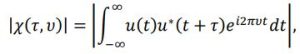
where u(t) represents the transmitted signal and u(t+τ) is the received signal, τ is the time delay, and v is the Doppler frequency. Figure 1 below shows an example ambiguity function showing Doppler frequency (v) which is related to the velocity resolution and time delay (τ) which relates to the range resolution.
![Figure 1. Ambiguity function of an LFM radar signal. [6]](https://www.rpmclasers.com/wp-content/uploads/2022/08/doppler-figure.jpg)
Figure 1. Ambiguity function of an LFM radar signal. [6]
The relationship between the signals time delay () and range (R) is fairly straight forward, 𝑅 = ½cτ where c is the speed of light. Therefore, it is fairly obvious that the less ambiguity there is in the time delay the finer the range resolution of the lidar system. To put this relationship in layman’s terms, the shorter the laser pulse the more accurately the system can resolve the distance to the target. Unfortunately, in order to accurately measure the Doppler shift (v) in the return signal its frequency must be precisely measured, which requires longer pulse widths. In fact, the frequency resolution of any digital detection system (Δf) is inversely proportional to its pulse duration (T) due to the mathematical principles utilized in fast Fourier transforms (FFT) to determined signal bandwidth. Therefore, the longer the laser pulse, the more accurately the system can resolve the targets velocity. This contradiction in signal requirements for improving the velocity and range resolution of a lidar system, is a perfect example of the uncertainty principle in action.
While this uncertainty can never be eliminated, there are several methods which have been developed over the years to work around this issue. The most common practice is by linearly modulating the frequency of the laser, the signal is essentially pulsed in frequency space, allowing a matched filter to be used to determine both the Doppler shift and range. In figure 2 it shows an overlay of the transmitted and received signals for a linearly frequency modulated (LFM) lidar signal demonstrating how both the Doppler shift and time delay can be determined. The ambiguity function for a typical LFM single was shown in figure 1, where it can be shown that the width of the center lobe is inversely proportional to the bandwidth of the frequency modulation. Alternatively, a laser can be phase coded to further improve the resolution, with typical examples being a Costas matrix [7] or pseudo-random phase-noise waveform [8].
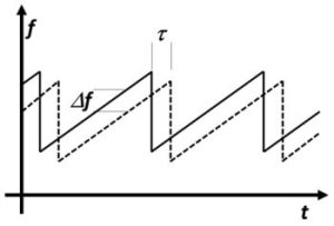
Figure 1. Linear Frequency Modulation (LFM) radar signal, overlapping the transmitted and revived signals.
All of these various lidar signal methods for measuring velocity have one critical requirement in common, the need for precise control over laser frequency. While a wide variety of single frequency lasers have been used in Doppler lidar research, the industry as a whole has adopted single frequency fiber lasers at the ideal light source.
Single Frequency Fiber Lasers
Fiber lasers have several advantages over traditional DPSS lasers all of which derive from the geometry of the fiber optic itself, namely the innate ability to have an extremely long single-mode optical cavity. This geometry allows for the production of either extremely high-power single-mode lasers producing unprecedented brightness, or extremely narrow band lasers with near perfect single frequency output. Most fiber lasers are erbium (Er) doped and lase at approximately 1550 nm, which corresponds to the peak absorption band of water making them eye-safe which is critical for the deployment of any practical lidar system. While single frequency continuous wave fiber lasers are ideal for Doppler lidar, it’s worth noting that fiber lasers can also be q-switched or mode-locked to produce high peak power, high energy, and narrow linewidth pulsed lasers. Pulsed fiber lasers are widely deployed in range finding and 3D mapping lidar systems.
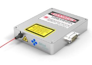
Figure 3 LRL2 Single Frequency Fiber Laser from BKtel.
One example of an ideal CW single frequency fiber laser for lidar is the LRL2, shown in figure 3, from BKtel. The laser provides a perfect TEM00 output beam with up to 1 W of output power and a linewidth of 10khz. The LRL2 has an operating range from 0° C to 65° C, with a wavelength drift of only 0.1 pm/° C, and extremely low relative intensity (RIN) noise as shown in figure 4 below. Not only are the optical characteristic of this laser ideal for lidar signal generation; it’s compact (120 mm x 100 mm x 20 mm), energy efficient (<30W power consumption) and rugged design make it ideal for integration in lidar systems in the harshest of environments.
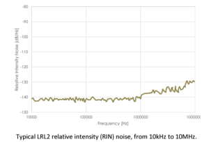
Figure 4. Typical LRL2 relative intensity (RIN) noise, from 10kHz to 10MHz.
About RPMC Lasers
RPMC Lasers Inc (Founded in 1996) is the leading laser distributor in North America. We are an OEM supplier working with the technology leading laser manufacturers from the US and Europe. RPMC supports the Industrial, Medical, Military, and Scientific markets. RPMC offers diode lasers, laser modules, solid-state lasers and amplifiers, ultra-short pulse lasers, microchip lasers, and fiber lasers and amplifiers. Also, we provide a wide range of custom solid-state lasers and laser diode subsystems.
References
[1] P. Lacomme, J. Hardange, J. Marchais and E. Normant: Air and Spaceborne Radar Systems, Norwich: SciTech Publishing, 2001.
[2] P. McManamon, G. Kamerman, and M. Huffaker, A History of Laser Radar in the United States, Proceedings of SPIE – The International Society for Optical Engineering, April 2010.
[3] G. Kamerman, Laser Radar Technology and Applications, (SPIE, 2003).
[4] P. Dong and Q. Chen LiDAR Remote Sensing and Applications, (CRC Press, 2018).
[5] N. Levenon and E. Mozeson, Radar Signals, (Wiley-Interscience, 2004).
[6] R. Chimenti, Sparse Frequency Linearly Frequency Modulated Laser Radar Signal Generation, Detection, and Processing, (University of Dayton, 2009).
[7] Golomb, S.W. and Taylor, H., “Constructions and Properties of Costas Arrays,” Proceedings of the IEEE, Vol 72, No. 9, 1143-1163 (1984).
[8] M. P. Dierking and B. D. Duncan, Periodic, pseudonoise waveforms for multifunction coherent ladar, April 2010Applied Optics 49(10):1908-22