 BUY NOW
 BK-FA-CW-SPACE
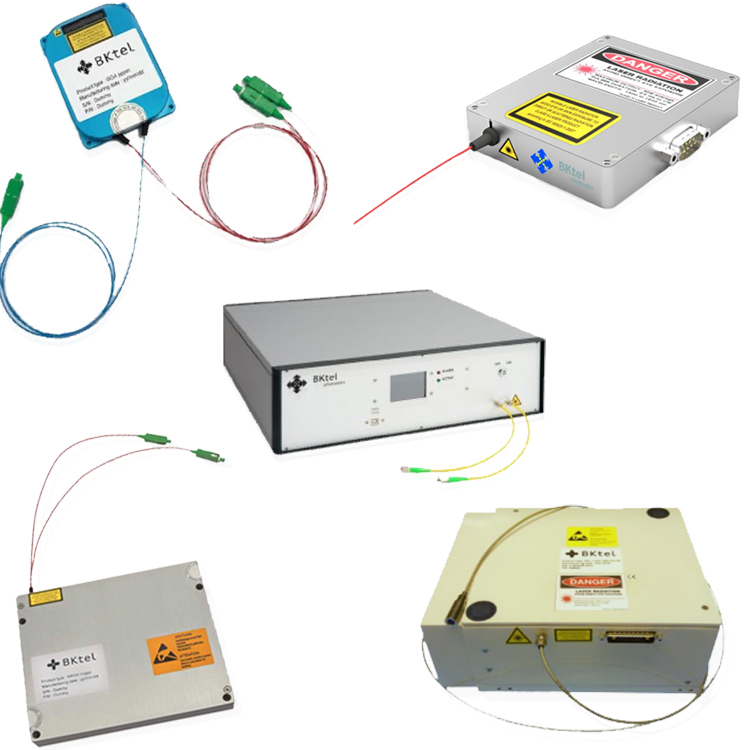
Space-grade 1.5 µm fiber amplifiers, 1535-1565 nm, from low-signal preamplification to 5 W-class spaceborne booster configurations
Key Features:
- 1 µm to 1.9 µm space optical communications amplifiers for intersatellite and satellite-to-ground links
- Low-signal preamplifier through high-power booster architectures
- Up to 5 W output on published space-grade booster configurations
- Compact space-grade amplifier formats with model-specific power, size, qualification status
- Receive-side options for very low input signals with optical monitoring and filtering options
- Ground-station booster and preamplifier architectures available for the other side of the optical link
Start by defining where the amplifier sits in the optical link – spaceborne transmit, receive-side preamplification, ground-station transmit, or a combined architecture – then narrow the optical power, gain, noise, SWaP, interface and qualification requirements.
Not sure where to start? Send RPMC the link role, wavelength, expected input level, required output power or gain, package constraints, environmental requirements & mission stage. We’ll help narrow the BKtel amplifier path.
POPULAR CONFIGURATIONS:
Picture |
Part Number |
Part Description |
Datasheet |
|
|---|---|---|---|---|
|
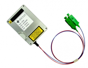
GOA2S |
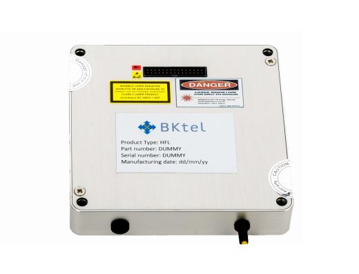
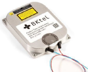
Space-Grade Fiber Amplifier, 1535 – 1565 nm, up to 10 mW, with collimator and FC/APC connector |

|
Get Quote |
|
CGOA2S |
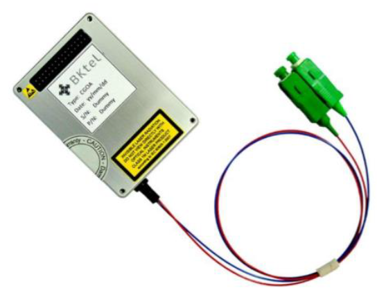
Space-Grade Fiber Amplifier, 1535 – 1565 nm, up to 2 W, with FC/APC connector |
|
Get Quote |
|
|
GOAS |
Space-Grade Fiber Amplifier, 1535 – 1565 nm, up to 1.3 W, with collimator and FC/APC connector |
|
Get Quote |
|
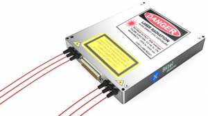
HPOAS |
Space-Grade Fiber Amplifier, 1535 – 1565 nm, up to 5 W, with collimator and FC/APC connector |
|
Get Quote |
Overview: BK-FA-CW-SPACE 1 µm – 1.9 µm Space-Grade Fiber Amplifiers
The BK-FA-CW-SPACE family provides 1 µm to 1.9 µm (including 1.5 µm “eye-safe” options) optical amplification for space-based free-space optical communication systems, including intersatellite links and satellite-to-ground optical links. Published space-grade amplifier configurations span compact low-power stages through higher-power booster architectures.
BKtel also supports very low-signal preamplification for receive-side architectures, along with combined preamplifier and booster configurations for systems that require both functions within a compact optical terminal.
The complete optical link may also require ground-side amplification. BKtel’s space communications portfolio includes higher-power ground-station boosters and low-noise preamplifier options, allowing the transmit and receive architecture to be considered as a system rather than as an isolated spaceborne component.
Technology readiness level, flight heritage, environmental testing and qualification status are configuration-specific. RPMC can help identify the appropriate amplifier architecture and confirm the current status and test requirements for the selected hardware.
Start Here by Defining the Amplifier’s Role in the Optical Link
BK-FA-CW-SPACE is the likely starting point when:
- You need space-grade 1 µm to 1.9 µm amplification for an intersatellite or satellite-to-ground optical link.
- The spaceborne transmitter needs additional output power from a compact booster amplifier.
- The receiver must detect and amplify a very weak incoming optical signal.
- Your optical terminal needs both receive preamplification and transmit boosting in one integrated architecture.
- The ground station needs a higher-power transmit booster, receive preamplifier or both.
- TRL, environmental testing, SWaP, optical interfaces or mission-specific qualification requirements influence the hardware selection.
If the application is terrestrial and does not require a space-oriented amplifier architecture, start with the BK-FA-CW fiber amplifier family.
Which Space Optical Communications Amplifier Path Should You Start With?
| Link Role | What the Amplifier Must Do | BKtel Starting Point | Key Selection Factors |
|---|---|---|---|
| Spaceborne Transmit Booster | Increase optical transmit power for an intersatellite or satellite-to-ground link. | GOAS, CGOA2S or HPOAS family depending on required power and current qualification status | Input power, output power, SWaP, thermal design, interface and qualification requirements |
| Low-Signal Receive Preamplifier | Amplify weak incoming optical signals while managing noise and signal quality. | GOA / GOA2S low-noise amplifier architecture | Minimum input level, output level, OSNR, filtering, monitoring and power budget |
| Combined Spaceborne Preamp + Booster | Provide receive-side preamplification and transmit-side boosting in one compact architecture. | Dual LNOA / HPOA configuration | Transmit and receive levels, noise figure, gain, housing size, vacuum requirements and terminal architecture |
| Ground-Station Booster | Provide substantially higher transmit power from the terrestrial side of the optical link. | BKtel ground booster, available with or without a preamplifier | Channel plan, output power, power-control mode, noise figure and end-cap or collimated output |
TRL, Flight Heritage & Qualification Are Configuration-Specific
BKtel’s space amplifier portfolio includes hardware at different technology-readiness and qualification stages. A TRL or flight-heritage statement for one amplifier configuration should not be assumed to apply to another output-power level, package or optical architecture.
RPMC can help confirm the current TRL, available heritage, environmental test history and any additional qualification requirements for the specific amplifier being considered for your mission.
How to Configure a BKtel Space Optical Communications Amplifier
The amplifier should be selected as part of the complete optical-link architecture rather than by output power alone.
- Define the amplifier’s location and role.
Identify whether the hardware is spaceborne or ground-based and whether it serves the transmit path, receive path or both. - Define the optical wavelength and channel plan.
BKtel’s current space communications amplifier portfolio is centered around the 1.5 µm C-band region, with published configurations covering 1535-1565 nm, but extends from 1 µm to 1.9 µm. - Specify the expected input signal level.
Transmit boosters and receive preamplifiers operate in very different input-power regimes, making this one of the most important early selection factors. - Set the required output power, gain and noise performance.
Transmit-side selection is usually driven by required optical power and gain, while receive-side selection puts greater emphasis on weak-signal handling, OSNR and noise performance. - Define SWaP and optical-interface constraints.
Provide package-size, mass, power-budget, fiber, connector, collimator, end-cap and terminal-integration requirements as early as possible. - Define environmental and qualification requirements.
Identify vacuum, temperature, vibration, radiation, test, heritage or TRL requirements that must be satisfied for the specific mission and program stage.
BKtel Space-Grade Fiber Amplifier Applications
BKtel’s 1 µm to 1.9 µm space communications amplifier portfolio supports transmit and receive functions across spaceborne optical terminals and terrestrial ground-station infrastructure.
Intersatellite Optical Links
Space-grade booster amplifiers can increase transmit power within intersatellite optical communication terminals where output power, SWaP, thermal design and current qualification status must be evaluated together.
Satellite-to-Ground Optical Communications
Spaceborne transmit amplifiers and receive-side preamplifier architectures can support optical links between satellites and terrestrial terminals across the 1.5 µm communications band.
Weak-Signal Receive & Pointing / Tracking Architectures
Very-low-input amplifier configurations can support weak-signal reception and optical monitoring functions used within pointing and tracking architectures. Published GOA / GOA2S configurations accept signals down to -60 dBm.
Optical Ground Stations
BKtel’s ground-station architecture includes C-band booster amplification up to 30 W, available with or without preamplification, for high-power transmit paths and complementary receive-side requirements.
What Does RPMC Need to Help Configure Your Space Optical Amplifier?
Send as many of these as you know:
- Spaceborne or ground-station hardware
- Transmit, receive or combined amplifier role
- Required wavelength or channel plan
- Expected input optical power or received signal level
- Required output power and/or gain
- Noise figure, OSNR or signal-quality requirements
- Polarization requirements
- Fiber, connector, collimator or end-cap requirements
- Package-size, mass and electrical power budget
- Control, monitoring or power-control requirements
- Vacuum, temperature, vibration, radiation or other environmental requirements
- Required TRL, heritage or qualification status
- Mission stage, quantity and project timeline
You do not need to identify the final BKtel model before contacting RPMC.
We can help translate the optical-link and mission requirements into the appropriate amplifier architecture and identify what still needs to be verified.
BKtel Space-Grade Fiber Amplifier FAQs
Common questions about BKtel 1 µm to 1.9 µm space-grade fiber amplifiers, FSOC booster and preamplifier architectures, ground stations, TRL and amplifier selection.
What wavelength range do BKtel space-grade fiber amplifiers cover?
BKtel’s current space optical communications amplifier portfolio is centered around the 1.5 µm C-band, with published space-grade amplifier configurations covering 1535-1565 nm but extends from 1 µm to 1.9 µm. Exact operating range can depend on the selected amplifier architecture.
Are all BKtel space amplifiers flight-qualified?
No. TRL, flight heritage, environmental testing and qualification status are model- and configuration-specific. RPMC can confirm the current status of the amplifier configuration being considered and help determine what additional qualification may be required for the mission.
How much output power is available from the space-grade amplifier family?
BKtel’s published space-grade amplifier portfolio includes configurations from low-power optical stages through booster amplifiers with output power up to 5 W. The appropriate power level must be considered together with SWaP, thermal design and current qualification status.
Can BKtel amplify very weak received optical signals?
Yes. BKtel’s very-low-noise GOA / GOA2S architecture is designed for low-input-power optical signals, with published input levels down to -60 dBm and signal monitoring that can support pointing and tracking functions.
Does BKtel offer amplifiers for optical ground stations?
Yes. BKtel’s current space communications portfolio includes a 1535-1565 nm ground-station booster with output power up to 30 W, power-control operation and options with or without a preamplifier.
Can a preamplifier and booster be integrated into one space-grade package?
BKtel has published a vacuum-tested dual preamplifier and booster architecture in a compact housing smaller than 155 x 155 x 30 mm. RPMC can help determine whether that architecture matches the transmit, receive and integration requirements of the optical terminal.
| Wavelength (nm) | |
|---|---|
| Description | Space-Grade Fiber Amplifiers, CW, 1 µm to 1.9 µm, up to 5 W output, radiation-hardened |
| Type | "Eye Safe", Airborne Laser, Low SWaP, Ruggedized, Fiber-Coupled, Customizable |