
 BUY NOW
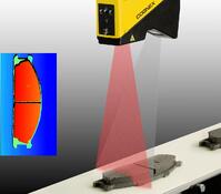
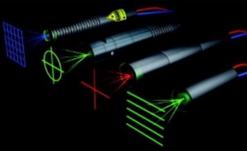
Machine vision can utilize a variety of schemes for image detection and analysis. Lighting can influence that analysis and lasers are often used to illuminate objects with structured illumination. This can be useful in providing additional information about the objects through image processing. Examples of information that can be obtained include defects, location, dimensions, dents, punctures, and alignment, for example.
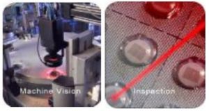 Figure 1: Applications of lasers to machine vision.
Both 2D and 3D imaging have a strong presence in industrial processing applications and have become cost-effective for consumer applications such as gaming or autonomous vehicle guidance. Using multiple lasers with different wavelengths helps to provide enhanced contrast or color data along with the image. Selecting the appropriate laser for your machine vision system depends on what you are trying to accomplish and the overall system architecture. While your system specifications are a good starting point, the system designer must know a little about lasers and how they are specified by their manufacturers in order to ensure they are making the correct purchase. Some specs will be obviously important to you, but others may not be so obvious until you get the laser in your system and wonder why it doesn’t work as intended. Many laser manufacturers are not machine vision experts, so it helps to know exactly what you want before you buy. Working with a laser specialist partner is beneficial and they can help you sort out the best laser for your system needs. This paper will help bridge that knowledge gap by presenting some of the more important laser specifications, and by discussing the various options available to the system designer.
Output Power
One of the first things a designer should know is how much optical power they need, and the corresponding classification of the laser at that power as determined by your respective regulatory agency. In the U.S., Class IIIa lasers are typically considered safe as their total collected radiant power collected by the eye is less than 5 mW. This means the optical power collected in a “7-mm-diameter circular aperture with a solid angle of acceptance of 10^-3 steradian with collimating optics of 5 diopters or less”.¹ Lasers exceeding the above optical power constraints, require the use of a controlled environment. Examples of higher power lasers include those used for medical, or material processing applications, where the risk of accidental eye exposure is controlled. You should always consult with a laser safety engineer prior to commercializing a product that uses lasers. For most systems that use visible cameras or photodetectors, 5 mW may actually be too much power, and attenuators may be incorporated into the system, or you may need to use an adjustable power supply. The system designer should try to characterize the system to determine the minimum and maximum optical power requirements.
COMPLIANCE GUIDE FOR LASER PRODUCTS (https://www.fda.gov/media/74026/download)
Laser optical power can vary over time due to power supply variations or aging of components. Does your system require power stability? If so, how much can be tolerated by your detection system? Some modules have feedback mechanisms to control power but might cost a little bit more. Power stability is often specified in terms of how much the power varies as a percentage of the typical or specified optical power. For example, over a 24-hour period, the power might be specified as <0.5%, and over the lifetime of the laser the stability might be <3.0%. If you need more or less stability, be sure to let your vendor know, but keep in mind that extreme specs may command a premium.
Wavelengths
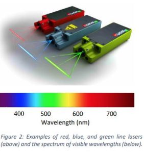
Typically, visible-wavelength lasers are used for machine vision systems, as cameras and detectors are readily available, and the beams are easier to align. Some circumstances can dictate the use of infrared or even ultraviolet lasers. The most common visible wavelengths include blue, green, and red. Wavelengths are expressed in units of nanometers (nm). Some of the most common colors and their wavelength ranges are blue (405-450 nm), green (532-550 nm), red (635-680 nm), as shown in Figure 2. In the near infrared portion of the spectrum, typical wavelengths that are used are: 830, 980, 1060, and 1550nm, but you can get many wavelengths in between. Try to understand if wavelength matters for your application, as some wavelengths are less expensive and others are available in higher power. If you need a green laser, but the exact wavelength doesn’t matter, let your vendor know you have a wide tolerance. An example of how you might spec this is: 540 ± 10 nm.
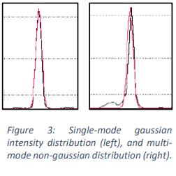 Lasers have other optical properties that are related to wavelength that may or may not be important to machine vision applications, but affect the price and quality of the beam. One is spatial mode quality. Lasers can produce a single spatial mode that produces a nicely uniform gaussian-shaped intensity profile. Some lasers achieve higher power by operating in more than one spatial mode, which is called multi-mode operation. A multi-mode beam profile or spot can look non-uniform and may fluctuate in intensity with time as shown in Figure 3. It is important to define if beam quality is important to your application, as is the case for most machine vision systems. If so, then you should specify a single mode laser.
Beam Shaping and Illumination patterns
Figure 4: Laser modules with various pattern generators.Lasers typically provide a narrow collimated light source that results in a circular or near circular spot on your target. Optics can be combined with the laser to focus the spot to a specific diameter, or even produce various illumination patterns. These can range from straight lines (single or multiple), point grids, crosses, circles, or even custom patterns (see Figure 4).
Optical Power Distribution of Lines
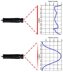
When specifying line lasers, the designer needs to understand the required line length, line width or thickness, the distance from laser to object, and whether intensity distribution across the line needs to be uniform.
Line length is usually specified as fan angle and can be set to anywhere between 10 and 90 degrees. The line length can be calculated once you know the fan angle and the distance from laser to object.
Line width and line thickness can be varied by adjusting the focusing optics. These can be pre-set by the manufacturer for a given object distance or controlled by the customer. You should specify if adjustability is an important feature.
There are two ways that lines are generated from a laser. The most common method is to use a cylindrical lens. The lens simply magnifies the light in one direction, which produces a line. The intensity distribution of this line is gaussian in shape, which means it will have a brighter center than the edges. Custom optics can be ordered to create a uniform power distribution, but usually for a slightly higher price. Note the differences in the intensity profiles in Figure 5 below and choose the type that is important for your application.
Environmental Considerations
Laser performance and lifetime are influenced by temperature and have a specified operating and storage temperature range. Before operating lasers, make sure they are within the specified operating temperature range or permanent damage can occur. Typical operating ranges might be -10 to +40C, or for some applications can go from -40 to +60C. Make sure you understand the typical operating range of your system and let your vendor know your constraints. Not only can laser power fluctuate with temperature, but the direction of the laser beam can drift slightly. The latter is referred to as pointing stability. As an example, it may be specified as <0.5 mrad over the operating temperature range. This parameter is usually more critical for long distance or very precise measurements.
Physical Characteristics
Lasers used for machine vision applications are typically provided in a module package that can incorporate beam-shaping optics, ESD protection, temperature control, LED
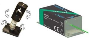
indicators, and the electrical interface. Laser modules are either aluminum cylinders or rectangular blocks with electrical connections on one end and the beam output on the other. You can also get fiber-coupled modules if you need to locate the laser remotely. Know your size constraints and be sure to check out laser module dimensions that accommodate your specific wavelength and optical power. Note that adding beam-shaping optics or temperature control will increase the size of the module. Also, the size of the module increases with output power as higher power requires a heatsink to dissipate the heat. All laser modules require a rigid installation. Cylinder modules can utilize an adjustable ring-type clamp, while other packages are simply bolted down (Figure 6).
A major packaging consideration is water resistance. Lasers can be designed for IP67 requirements, thus resisting water and moisture in adverse environments.
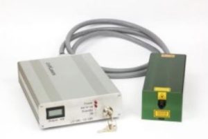
Modules can be purchased with or without power supplies. Many OEM integrators choose to provide their own power source, and only need to provide a stable 5 or 24 VDC input. For those looking for a turn-key solution, a 120/240VAC power supply can be provided with the laser. An example is shown in Figure 7. It is important to note that lasers are sensitive to voltage spikes and in particular to electrostatic discharge (ESD). Commercial power supplies typically provide a certain level of protection to keep the lasers free from excessive voltage spikes or accidental over-voltage. Another consideration is compliance with local regulatory agencies. In particular, the CDRH governs laser safety in the U.S. and a turn-key system should be compliant with those requirements. If you choose to integrate your own power supply, make sure you are familiar with laser safety, heat sinking, ESD protection, and noise-free constant-current control.
For applications that require intensity modulation, most modules can accommodate TTL modulation up to 1 MHz (532 nm up to 10 kHz) or analogue modulation up to 50 kHz. You should specify if this is an important feature for your system.
About RPMC Lasers Inc.
RPMC Lasers Inc. (Founded in 1996) is the leading laser distributor in North America. We are an OEM supplier working with the technology leading laser manufacturers primarily from the U.S. and Europe. RPMC supports the Industrial, Medical, Military and Scientific markets. RPMC offers diode lasers, laser modules, solid-state lasers and amplifiers, ultra-short pulse lasers, microchip lasers, and fiber lasers and amplifiers. In addition, we offer a wide range of custom solid-state lasers and laser diode subsystems.
RPMC Lasers would love to be your laser partner. Our experienced Product Managers are eager to help in defining the right laser for your experiment or instrument and if one of our suppliers is the best choice for your laser, we are happy to send a quote. If we do not have the right laser, we are pleased to introduce you to the company that does. Call us to discuss your needs and see how we can help you be a success.