
 BUY NOW
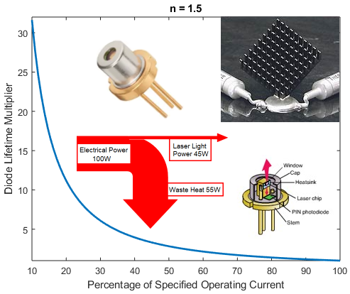
Overview:
Over the years, laser diode development has led to increased output power, which is excellent for many applications, except you are now contending with added waste heat. The mounting or heatsinking of the laser package is of tremendous importance because operating temperature strongly influences laser lifetime and performance. Effectively achieving correct mounting or heatsinking of the laser package is not as simple as many would assume. This article will discuss the various package types and the best practices for ensuring the laser diode is mounted correctly. Ensuring the laser diode is mounted correctly will provide the best performance and most extended lifetimes.
Laser Diodes (Semiconductor Lasers):
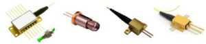
Laser diode is a generic term that includes several different semiconductor lasers and many additional types of housings or packages for these semiconductor lasers. The more common types of semiconductor lasers include:
1. Fabry-Perot Laser Diodes – This is the simplest form of laser diode, typically called edge emitters. These lasers can be single-mode, multimode, or used as an array of emitters (bar) to achieve much higher powers. Available in the UV, visible, and infrared wavelengths.
2. Stabilized Laser Diodes – This type of laser diode utilizes an optical element to introduce feedback into the laser cavity. This feedback mechanism can be internal or external to the actual laser cavity. Some examples include Distributed Bragg Reflector (DBR) lasers, Distributed feedback (DFB) lasers, and external-cavity (EC) lasers. Available primarily in the visible and infrared wavelengths.
3. Vertical-Cavity Surface-Emitting Lasers (VCSEL) – VCSELs have an optical cavity perpendicular to the mounting surface. VCSELs have advantages such as circular beam profile and reduced speckle. Available in visible and infrared wavelengths.
4. Quantum Cascade (QCLs) and Interband Cascade Lasers – QCLs are intersubband semiconductor lasers emitting in the mid-infrared (MWIR) to far-infrared or long-wave infrared (LWIR) portion of the electromagnetic spectrum from 4 to 16 µm. Fabry-Perot QCLs provide quasi-continuous wave (QCW) multimode output. Distributed feedback (DFB) QCLs provide continuous wave (CW), single-mode output with narrow line widths. Available in the mid-infrared wavelengths.
These semiconductor lasers are called laser diodes, and most, if not all, of the advice and mounting procedures discussed below, apply to all laser diodes.
Laser Diode Housings and Packages:
Most of the laser diode types discussed above are available in many different housings or package types, depending on the output power of the laser and the options needed. We will group these package types into the following groups: Open Packages, Sealed Packages, and Fiber-Coupled Packages. Each group has some specific requirements and concerns to achieve the best performance. Before we get to the specifics for each package group, here are some general advice and precautions applicable to all laser diodes.
General Advice and Precautions for all laser diodes:
1. Laser Classification – You should know the classification of your laser and take the necessary precautions to avoid direct or indirect laser light. Medium and high-power lasers are potentially hazardous because they can burn skin or even the eye’s retina. To control the risk of injury, various specifications, for example, 21 Code of Federal Regulations (CFR) Part 1040 in the US and IEC 60825 internationally, define “classes” of laser depending on their power and wavelength. Alternatively, you can purchase a fantastic Laser Safety Guide from the Laser Institute of America to keep on hand: https://www.lia.org/store/product/laser-safety-guide. This guide covers safety standards, hazard classification, eye protection, etc.
2. Eye Safety – Working with lasers can be dangerous, especially to the naked eye. Laser goggles, protective enclosures, etc., should be used in addition to safety equipment such as “Laser Active” signs, door interlocks, and switches. Ideally, diode lasers should operate in a sealed, light-tight box equipped with interlock switches that cause the laser to shut down when the enclosure is open instantly.
3. Electrostatic Discharge (ESD) – Most laser diodes are very sensitive to damage by electrostatic discharge (ESD) or other voltage transients. ESD procedures are required when handling laser diodes. During shipment, the laser diode will be in a conductive plastic bag, and when possible, the anode and cathode electrical contacts are shorted together to prevent ESD damage. When the laser is not connected to a power supply, the user should also short the anode and cathode electrical contacts. All persons and tools that may contact the laser must be continuously grounded, for example, with a grounding strap. A grounding strap is a device worn by the user that creates an electrical connection to ground. This measure protects electronic equipment from electrostatic discharges that could damage or destroy the laser diode.
4. Unpacking – Before opening the conductive plastic bag, choose a clean environment where you will unpack the diode lasers and keep them there for at least 4 hours to achieve thermal equilibrium. The handling personnel and the tools used for handling must be grounded for ESD-protection purposes. During handling, the personnel should wear clean gloves and use plastic tweezers to avoid contaminating the facets of the laser. Some lasers may be secured to a transport plate by fixing screws. Understand which screws are fixing screws and which screws are part of the assembly. Do not loosen the assembly screws which keep the diode laser together. The fixing screws may also be the short-circuit between the anode and cathode electrical contacts to prevent ESD damage. The laser diodes must be kept in a clean and dry atmosphere with a temperature range of 0°C to 60°C once removed from the shipping containers.
5. Cleaning – Solvents, plastics, glues, and heat conductive paste are not allowed near the laser diodes. These substances can outgas and deposit on optical surfaces, including the laser diode facets. The laser diode front facet is extremely sensitive and must be kept free of contamination (e.g., dust, water, gas, etc.). Any contamination on the laser’s front facet will lead to irreversible damage and failure of the laser diode, even if there is no sudden failure. There is no way to clean the front facet of a laser diode. The semiconductor crystal and its coatings are very sensitive to any kind of solvents and liquids, and mechanical methods could damage coatings or the facet itself. Do not touch the laser front facet with any object!
6. Laser Diode Driver – The operation of laser diodes relies on using an approved laser diode driver that is current-regulated and designed explicitly for laser diodes. Off-the-shelf power supplies can deliver a high current spike upon energizing or produce a very short duration reverse biasing when turning off the unit. Either of these instances will damage or destroy the diode laser. Laser diodes are very sensitive to current and voltage spikes. Current and voltage spiking must be avoided when switching the power supply on and off and when operating the diode laser. The residual ripple of the current must not exceed a value of +/- 10 %. The diode driver should also include a safety circuit that switches the system off within approximately 100 ms in the case of faults. Faults are all conditions that put the safety of persons or the device at risk. Read a more in-depth article on laser diode drivers: “Why Shouldn’t You Voltage Drive a Laser Diode?”
7. Electrical Connections – Most laser diode drivers have a provision to disable the supply and short the output to allow for connection of the diode. Never make the connection to the laser diode with the power supply voltage on.
8. Thermally-conductive Compounds – Pastes are typically not recommended for lasers. The liquids contained in these pastes liberate gas over time and can deposit on optical surfaces. Also, over time the initially homogeneous distribution of the paste can change to a mixture of conductive and non-conductive areas. This separation will impair the heat transfer from the laser.
9. Back Reflections – Some laser diodes are susceptible to damage from back reflections into the device. Thissusceptibility is more common with lower wavelength material than with higher wavelengths. Thus, if
attempting to collimate the output, or if there are optical components in the optical path, be careful to avoid back reflections. Back reflections can be more of an issue with fiber-coupled or FAC lensed lasers because the optics help focus the back-reflected light into the laser, ensuring catastrophic failure.
10. Flammable Materials – All matter exposed to laser radiation is subject to heating by absorbing radiation energy. Preclude exposure of flammable or combustible material to the radiation. Flames, smoke, and soot all have harmful effects on equipment, electronics, and optical components.
11. Noxious Substances – By the interaction of laser radiation with exposed materials, substances may be generated as aerosols, gases, or dust, harmful to health. Therefore, installing an appropriate exhaust device is critical, and care needs to be taken to clean the exhaust air for the specific application adequately.
12. Laser Lifetime – Generally, the end of life of a high-power diode laser is reached at the point in time when the output power at constant current shows a reduction of 20%. The operation current can be increased by up to 20% to counter the effect of power loss, maintaining the nominal optical output power. This laser diode lifetime rule is defined differently on some types of laser diodes.
General Thermal Management Advice and Precautions:
1. Waste Heat – Many customers do not appreciate the importance or the complexity of removing waste heat. Heat is the most significant cause of field failures, especially for higher power laser diodes. You must remove waste heat efficiently and instantaneously or the laser will be catastrophically damaged or, at a minimum, experience a shortened lifetime. One of our previous blogs, titled “Understanding Laser Diode Lifetime,” will provide further reading on some critical aspects that affect the lifetime of a laser diode, including die mounting, facet damage, and drive current.
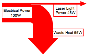
You must ensure the laser diode has an adequate heatsink for the waste heat produced. Depending on the semiconductor laser type and wavelength, laser diodes are typically 10 – 60% efficient at converting electricity into optical output power (laser light). The remaining energy not converted into light is converted into waste heat. A simple method for determining the amount of waste heat is to take the total input power (Amps*Voltage=Input Power Watts) minus the optical output power (Watts). The balance is the amount of max waste heat in Watts. The laser diode die will always run hotter than the surrounding components, package, and the heatsink. With all the generated heat confined to a small area within the package, ensuring a solid and secure connection to an adequate heatsink is critical for transferring this heat.
Effectively transferring heat between two surfaces, in this case between the base of the TO-Can package and the mounting surface of a heatsink, typically comes down to two main factors. These two factors are the thermal conductance of the package and heatsink materials and the thermal resistance (impedance) of the interface between the two. The higher the impedance, the lower the rate of heat transfer. Minor, even microscopic imperfections in the surfaces of the two components create tiny gaps when joining these surfaces together. Suppose these gaps are filled by an insufficient material such as air, with low thermal conductivity. In that case, the interface will exhibit a high thermal resistance, impeding the efficient transfer of heat from the package to the heatsink. There are some primary considerations when attempting to minimize the interface’s thermal resistance:
- How efficiently the materials conduct heat.
- How minimizing surface imperfections introducing compression force can reduce gap size
- How thermally conductive the material is, used to fill any remaining gaps.
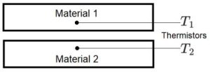
The following equation is useful for calculating the thermal resistance or impedance between two materials using two temperature sensors (thermistors):
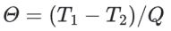
T = Temperature (ºC)
Q = Heat (W)
Θ = Thermal Resistance (ºC/W)
2. Operating Temperature – Most lasers have a recommended operating temperature and a location where this temperature is measured. Suppose you run a laser diode at a temperature higher than recommended. In that case, the lifetime of the laser will reduce exponentially as the operating temperature increases above the recommended temperature, perhaps to the point of catastrophic failure. Diode laser degradation accelerates with increased temperature. Operating at a temperature lower than recommended for many laser diodes can slightly increase the output power (higher efficiency), improve lifetime, or both. Therefore, one should minimize the operating temperature when feasible. However, lowering the diode laser temperature below 15 °C is only suitable in a hermetically sealed housing with a dry inert atmosphere (e.g.,Nitrogen), as condensation will irreversibly damage laser diodes. For example, GaN (gallium nitride) and AlGaN (aluminum gallium nitride) laser diode facets will immediately oxidize when exposed to oxygen.
3. Heatsinks – Most all laser diode packages will need some form of heatsinking. The heatsink must be capable of dissipating the waste heat generated by the laser. Lower power devices may only need to be mounted to a baseplate. However, higher power devices require a more substantial heatsink or a forced air, finned heatsink, and laser diodes arrays (bars) may need active cooling to handle the waste heat. Furthermore, suppose the specific laser diode die is not temperature-sensitive. In that case, you can consider a smaller package size and a simple heatsink, as that die can operate with negligible wavelength and power fluctuations due to changing temperatures. However, if the die is temperature-sensitive, then a more substantial heatsink, and perhaps a larger package, would be necessary to maintain a constant temperature and avoid fluctuations in performance. There is more surface area to transfer heat more efficiently with larger package sizes.
The best heatsink material is copper, but aluminum is also a suitable heat conductor. The surface should not be anodized in the region where the laser package contacts the heatsink if aluminum is used. The aluminum oxide anodized coating makes an effective thermal insulator which is detrimental for heat transfer. The heatsink surface should be machined flat and smooth where it will contact the mounting surface of the laser package to allow for efficient heat transfer. The heatsink surface should be finely milled or lapped (flatness: 0.5 μm, roughness: 0.5 μm), clean, and free of scratches to guarantee good thermal contact. High-quality, void-free bonding of the package to the heatsink lowers the overall impedance for efficient heat dissipation. For further reading on mounting and heatsinking pitfalls, check out our article, titled “The Three Most Common Mistakes When Mounting and Heatsinking a TO-Can.”
The heatsink may be cooled by air, water, or a thermoelectric cooler (TEC). Depending on the type of laser, an air-cooled heatsink may provide sufficient cooling. An air-cooled heatsink can maintain an operating temperature a few degrees above your ambient temperature if sized correctly. However, if the ambient temperature changes, the heatsink temperature will also change. This temperature change will not provide stability of the laser wavelength and output power. Most often, active cooling of the heatsink is necessary. Actively cooled heatsinks offer much better heatsinking performance and introduce temperature control into the system. Active cooling usually is either water-cooling or thermoelectric coolers. The most straightforward design of an actively cooled heatsink is a metal plate with a cooling hole that allows coolant to flow through the heatsink. Typically, the coolant liquid is water for ecological reasons and because of its high heat capacity.
4. Thermal Spacer – In permanent installations, using a silver-filled epoxy at the interface can improve the heatsinking effectiveness. However, if using silver-filled epoxy, ensure that it is a “space-qualified,” low outgassing type to avoid contamination of the laser facets (Epoxy Technology H21D, for example). An indium foil spacer can be used to reduce the thermal impedance of the laser package to the heatsink interface. However, in our experience, indium foil offers a negligible improvement over a good copper-to-copper interface.
5. Temperature Drop Check – When testing out a heatsink configuration, it is wise to test the temperature drop between the laser package and the heatsink using a very small thermocouple touched to the base of the laser package. The temperature drop during laser operation should be only 1-2° C.
6. Wavelength Check – Another test for the heatsink configuration is to check the laser emission wavelength at the specified current and operating temperature. A much longer wavelength than specified on the datasheet supplied with the laser indicates bad thermal contact and thermal overload of the diode laser. Therefore, you must improve the thermal contact before continuing laser operation. The laser emission wavelength will change with operating temperature: the wavelength increases approximately 1nm for every 4° C temperature increase (~0.25nm/K). This value varies by wavelength.
Advice and Precautions for Open Packages:
Open heatsinks provide little to no protection for the delicate laser chip. The laser chip is very fragile and must be protected from any mechanical contact or contamination. The exposed laser facets (mirror coatings) must not be contaminated with any foreign material to help ensure long lifetimes.
General Precautions for Open Packages:
1. Heatsink – All laser diodes in an open package must be attached to a heatsink before operation (discussed above in General Thermal Management – Section 3).
2. Keep the Laser Diodes Clean – Open Packages should not operate in an environment where dust particles in the air can reach the diode’s active region (output facet). The laser facets are sensitive to the accumulation of dust. High electrical fields near the active region attract dust particles that cause irreversible damage to the facets during operation. As the dust particles enter the intense optical field at the laser facet, they burn, and the residues accumulate in the laser facet. This dust accumulation will occur unless the laser operates in a true “class 100” cleanroom environment, even in a seemingly clean “lab environment.” This kind of contamination does not occur very rapidly. Instead, over several hundred hours of operation in a normal room environment, an open heatsink laser will show tiny “specks” on the facet of the laser under microscopic examination. These will gradually degrade the laser prematurely. Cleanroom class 10,000 for handling and cleanroom class 100 for operation is highly recommended for open packages. If an open heatsink laser operates outside of a cleanroom for more than short periods, it should be packaged within a sealed container to prevent this dust accumulation. This package does not require a proper hermetic sealing of the laser. An epoxy seal or O-ring seal around the laser assembly is sufficient.
3. Facet Contamination – Contamination of the laser facets can cause immediate and permanent damage to the laser. You should never blow on the laser, or expose the laser to smoke, dust, oils, and adhesive fumes. Avoid touching optically active surfaces of the laser, such as the laser chip, micro lenses, optical elements, and beam-exit windows. Contamination of the optical surfaces will lead to the destruction of the laser. There is no way to clean the front facet of the diode laser! During handling, all personnel should wear clean gloves and use plastic tweezers to avoid contamination of the facets of the laser.
4. Thermally-Conductive Compounds – Personnel should never use thermal grease with open heatsinks. Most thermal greases tend to “creep.” The material will eventually contaminate the diode facets.
5. Keep the Laser Diodes Dry – Keep the laser diode facets dry. The operation of open laser diode packages in high humidity environments can damage the optical coatings, causing the laser to fail. Never operate a laser below the dew point. The dew point is the temperature, starting from which condensation of the humidity in the air at the diode laser begins. The relative humidity must not exceed 85% (no condensation). Because of possible fluctuations, we recommend aiming at a mean relative humidity of maximally 60 %.
Precautions for Specific Open Packages:
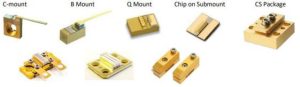
C-Mount Package:
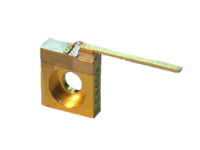
1. Mounting – To operate, the C-mount must be screwed down securely to a heatsink using a #2-56 (English) or M-2 (metric) screw. The C-mount has a shallow counterbore around the mounting hole for applications that require close mounting of a component in front of the laser. Personnel can use a shallow binding head screw or a button head cap screw in this situation.
2. Electrical Connection – The copper C-mount is the laser diode anode (+) terminal, so it is best to connect the power supply anode to the heatsink. Do not attempt to solder directly to the copper C-mount. The laser diode cathode (-) terminal is the wire lead attached to the C-mount. Connection to this lead can be made either by soldering or by using a small, high-quality spring contact socket. The best sockets of this type have four contact fingers, and the fingers are gold-plated (see parts made by Mill-Max, for example).
3. Soldering Heat – Personnel must take great care if soldering to the cathode wire lead. It is best to perform soldering with the C-mount already attached to the heatsink. This approach will prevent the body of the laser from heating up excessively. The cathode lead itself can withstand high temperatures, but the main part of the laser block must remain at <120°C.
4. Soldering Fumes – The laser can also be damaged by contamination of the laser facets with solder flux fumes during soldering. Typical rosin-core electronics solder generates a cloud of smoke when heated by a soldering tool. This smoke will coat the laser facets, and permanent facet damage will occur. If it is necessary to solder near the laser diode, the diode should be covered to prevent this contamination. One method is to use a loose-fitting piece of aluminum foil to carefully cover or block off the area around the laser chip. The chip and the wire bonds are very fragile, so the foil must be applied carefully without contacting the laser chip. Also, consider using a fume extractor to catch the fumes.
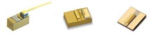
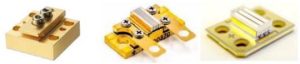
Q-mount, B-mount, Chip on Submount (COS), and Other Open Heatsinks:
1. Mounting – These open heatsinks must be securely attached to a heatsink to operate correctly.
2. Heatsinking – Attaching these open packages to a heatsink is critical. This can be accomplished by either using a low-temperature solder or a silver-filled epoxy at this interface. If silver-filled epoxy is used, it should be a “space qualified” low outgassing. To avoid contamination of the laser facets (Epoxy Technology H21D, for example). Great care must be used if soldering the package to the heatsink. The laser must remain <120°C to prevent the laser from reflowing and/or damaging the laser.
3. Soldering Fumes – See section 4 directly above, under C-Mount Package
4. Electrical Connection – The base material on these package types varies. Copper, CuW (Copper Tungsten), and ceramics like BEO and AlN are often used. The laser may or may not be isolated from the heatsink, depending on the base material. If an electrically conductive material is used, the base is the laser diode anode (+) terminal, so the power supply anode connection is best made to the heatsink. If an electrically isolated material is used, the anode connection is typically a pad on the laser chip’s surface. The laser diode chip should be covered to prevent contamination when soldering to this pad.
Sealed Packages:
Sealed Packages or windowed packages are hermetically sealed at the factory prior to shipment. Sealed packages offer lower risk because the laser diode chip or laser diode bar is protected from dust, mechanical damage, humidity, out-gassing, etc.… Smaller, sealed packages are typically conductive cooled, but larger and/or higher power packages can be actively cooled with either an internal TEC or water-cooled. Also, check out our blog: “Three Most Common Mistakes When Mounting and Heatsinking a TO-Can.”
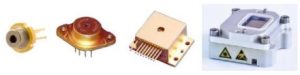
9mm Package, 5.6mm Package, 3.8mm Package, TO type packages.
1. Heatsink – It is important that the Copper portion of the base be in good contact with the heatsink to achieve optimal heat extraction from the laser package.
2. Avoid – Not all parts of the TO-type packages are made of copper. The window, cap, and the portions of the base to which it is attached are made of steel, which is a poor thermal conductor.
3. Mounting – The preferred method for mounting these packages is clamping the package to the heatsink. The clamp should have a hole for the cap, and the clamping force should be applied to the header flange.
TO-3 Package, HHL Package, and other sealed packages
1. Mounting – The package must be screwed down securely to the heatsink using the proper screw size and recommended torque.
2. Heatsinking – The laser package should be cooled well enough that the temperature rises no more than 40-45°C during operation. The heatsink must be able to dissipate the heat generated by the laser and the TE cooler if installed.
3. Avoid – The heatsink surface should be machined flat and smooth so that the base of the package is not bent when the screws are tightened. Screwing the package to a heatsink that is not flat could potentially fracture the TE cooler inside of the package.
Fiber-Coupled Packages:
1. Mounting – The package must be screwed down securely to the heatsink using the proper screw size and recommended torque.
2. Heatsinking – The laser package should be cooled well enough that the temperature rises no more than 40-45°C during operation. The heatsink must be able to dissipate the heat generated by the laser and the TE cooler if installed. Higher power fiber-coupled packages may be equipped with a water-cooled base plate, a water-cooled special heat exchanger (DCB)/PAT_DCB/thermoelectric coolers (TEC).
3. Avoid – The surface of the heatsink should be machined flat and smooth so that the base of the package is not bent when the screws are tightened. Screwing the package to a heatsink that is not flat could potentially fracture the TE cooler inside of the package. Many of the fiber-coupled packages include a short-circuiting bridge during shipment for ESD. It is not designed for conducting a high current. If a current of more than 5 A should flow through the short-circuiting bridge for longer than 3 seconds, the insulation of the internally laid cables heats up. Remove the ESD shorting prior to operation of the laser.
4. Water Cooling – Suitable hoses must be used to connect water-cooled modules. We recommend tube material by SMC (www.smc.com), type TRBU. The cooling water quality to be used with water-cooled plates must correspond to normal industrial quality tap water. A coarse filter must be included in the water-supply system only if a particle size of < 500 μm cannot be ensured. When using DCBs, a particle size of < 100 μm must be ensured.
5. Fiber Bending – Special care needs to be taken with fiber pigtailed laser diodes. The fiber should not exceed the minimum bend radius of the fiber. The fiber type and core diameter define the minimum bend radius.
6. Fiber End Faces– Typically, the fiber is terminated with an SMA connector. The cap should be replaced if the laser is not in use. The end of the fiber is very susceptible to damage if it is not handled correctly. Absolute cleanliness of the end faces of the fiber is crucial for the perfect operation of the diode laser. Before starting the installation, check the end faces of the fiber for contamination or mechanical damage using a microscope at a magnification of at least 20x. Contamination on end faces will at least cause a loss in power or heating of the fiber. In the worst case, the fiber can burn off, thereby contaminating the diode laser’s output window.
Laser Diode Arrays (Bars):
Laser diode chips consisting of a single emitter, as shown in the packages above, are limited in their output power by the amount of power from the emitter. Several or many emitters can be united in a single chip for much higher output powers. These chips with multiple emitters are called laser diode bars. Theoretically, it would also be possible to mount several single emitter chips onto one heatsink and integrate them onto a common mechanical base. But laser diode bars are used due to the simplified handling and the higher precision of the spatial arrangement of the individual emitters obtainable with bars.
A high-power laser diode bar package is a sensitive electronic component. To ensure long lifetimes and troublefree operation of the high-power diode laser, you must have a thorough understanding of the package design, the operating principle, and the properties of the diode laser. This understanding is also required for an adequate heatsink design and diode driver selection.
Open Bar Packages – Passive (Conductive) Cooled Packages:
1. Mounting – The bar package must be screwed down securely to a lapped heatsink using the proper screw size and recommended torque to operate correctly.
2. Heatsinking – The heatsink must be able to handle the waste from the laser diode bar package. A water-cooled cold plate is often used for bar packages. The cooling water quality to be used with water-cooled plates must correspond to normal industrial quality tap water.
3. Electrical Connection – For some of these bar packages, typically single bar packages, the copper base is the laser diode anode (+) terminal. The laser diode bars are electrically isolated for other packages, typically stacks of bars. Consult the drawing to determine if the laser diode bar(s) are electrically isolated. If not electrically isolated, all laser diode bars are soldered with the p-contact to the heatsink. Thus, the heat sink is always the p-contact! The electrical connections of some laser diode packages are connected to the diode laser through cable lugs, ring tongue terminals, and the laser’s mounting screws. Pay special attention to the correct polarity!
4. Electrical Isolation Not Needed – If the laser diode bar is not electrically isolated from the base and the
mounting plate does not need to be potential-free, the diode laser can be mounted onto the mounting plate directly or by means of a soft, metal contact film. Suitable film materials include, for instance, InSn of a thickness of 25 μm or In film having a thickness of 50 μm. Take care to ensure that the film is attached to the entire mounting surface of the bar package.
5. Electrical Isolation Needed – If the diode laser must be electrically insulated from the mounting surface, insulation may be achieved by a thin flat ceramic plate of high thermal conductivity. Plastic insulation foil (e.g., Kapton) will affect laser lifetime because of increased thermal resistance and possible solvent emerging that might damage the semiconductor crystal. Even highly thermally conductive ceramic plates have a higher thermal resistance than, for instance, indium films, an additional temperature difference between the heatsink temperature and the cooling-plate temperature will appear. The heat sink temperature must not be increased beyond the permissible value, as this would involve a higher degradation rate. If necessary, the optical output power should be limited, or the cooling-plate temperature lowered. For more information on suitable films, contact RPMC.
Open Bar Packages – Actively Cooled Packages:
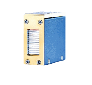
High-power laser diode bar stacks require a very efficient, actively cooled package due to a large amount of waste heat in a small area. Microchannel cooled heatsinks (MCHS or MCC) are based on the principle of convective heat transfer. The heat is transferred from the bar to a thin, mostly metal substrate and then to a liquid coolant flowing through it. The MCC is a stack of several layers that define the cooling medium’s route in an optimized path directly under the mounting surface of the diode laser bar. The cooling capacity of the heatsink determines the power level at which the laser diode bar can be operated. The better the cooling, the higher the output power and lifetime from the bar. The lifetime will be negatively impacted if the laser diode bar operates at a higher operating temperature.
1. General Cooling – For the best cooling, the microchannels in the MCC are small, ~40 – 400 μm by typically 300 μm high. High flow rates of the liquid coolant provide ideal conditions for the convective heat transfer from the copper to the coolant. Flow rates too high will increase the mechanical abrasion in the cooling channels; flow rates too low will result in a diminished cooling and higher operating temperature.
2. Detailed Cooling – The cooling system requirements for MCHS are very specific and critical for good lifetimes. The general requirements are:
a. Deionized water
b. Filters to maintain particle size: < 15 μm
c. An ion exchanger cartridge to keep the conductivity at 2..10 μS/cm.
d. Do not use any material that, in combination with copper, would form galvanic elements (e.g., aluminum, zinc, brass).
e. Plastics must be free of chlorine and additives, especially plasticizers (softeners) that can be washed out (suitable for deionized water, recommended: food grade).
f. When using high-grade steel, we recommend using the alloys X5CrNi 1810 or X6CrNiMoTi 17122 (i.e., you should use sulfur-free V4A alloys).
g. The flow rate should be 300 ml/min ± 10 % (corresponding to 18 l/h ± 10 %). This flow rate must be multiplied by the number of submounts used on the stack. For instance, on a stack with six submounts, the prescribed flow rate is approx. 1.8 l/min ± 10 % (corresponding to 108 l/h ± 10 %).
h. Avoid bubble generation and superficial oxygen intake
3. Water Connections– Typically, different size hoses are used for the plug connections. Hoses with the correct outer diameter must be used. We recommend hoses by SMC (www.smc.com), type TRBU, to be used because they are flexible and simultaneously vapor-tight. Actively cooled packages will require O-rings. The O-rings must be resistant to deionized water and reach a compression of 20 – 30 % of their normal thickness.
4. Cooling Precautions – Before every turn-on and connecting to the laser diode package, the cooling system must be operated for at least 20 min in coolant-side short-circuit mode until the specified conductivity is reached using a commercially available conductivity meter. As a rule, the chiller reservoir is the best place accessible for this measurement. Compare this measurement to the possibly existing remote software measurement. Operating the system in this manner also guarantees no particles get into the microchannels of the laser diode package and cause irreversible damage due to reduced cooling. After the operation of the cooling system in short-circuit mode, the coolant hoses are to be connected to the actively cooled stack. Before and after connection to the MCC stack, check for leaks. If you find any leaks, instantly turn the cooler off. If the coolant connectors that are closest to the diode laser are leakproof, check the other connectors and joints. Avoid getting any coolant on the diode laser!
5. Freezing – The storage temperature for MCCs is limited to the freezing temperature of the liquid coolant. At low temperatures, residual moisture in the microchannels may freeze and mechanically destroy the microchannels. Even after removing the coolant and purging the cooling channels with nitrogen or clean oilfree air, residual moisture may remain inside.
6. ESD Caution – When a stack is shipped, it is electrically shorted to a metal base plate to protect against
electrostatic discharge (ESD) and sealed into a conductive plastic bag. Once removed from the bag and these screws are removed, the stack is no longer protected from ESD damage.
7. Electrical Connections & Polarity – The electric cables are connected to the diode laser through cable lugs and ring tongue terminals at the specified locations with the screws supplied. Pay special attention to the correct polarity! Keep the electrical cables as short as possible. Electrical cables should be arranged in a lowinductance constellation to avoid any tendency towards current oscillations. The case and the base plate of the MCC assembly are potential-free (Electrically Isolated).
8. Applying Current – Make sure the nominal current of the diode driver has been set to 0 amps. Turn on the diode driver. Most diode drivers provide an additional switch for enabling the current to flow. If your driver contains such a switch, actuate it now. Increase the current to approx. 1 – 1.5 A. The correlating voltage should now amount to about 1.6 – 2 V per bar. Then, increase the current slowly until the output power is to the desired value. Never exceed the rated output power specified in the product datasheet.
There are many different laser diode packages. We tried to supply enough general advice and precautions so that regardless of the laser diode package you have, you will have a basic understanding of the requirements needed to properly mount the laser for optimum lifetimes and performance.
If you have any questions about mounting your laser or the operation of your laser, be sure to get in touch with us immediately. We are happy to help. We want you to be successful!