
 BUY NOW
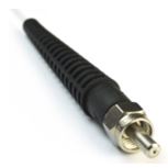
Introduction
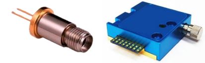
Fiber-optic beam delivery offers many advantages over free-space laser diodes. Fiber-coupled laser diodes deliver light efficiently to the desired location while providing additional optical, mechanical, and integration benefits.
Depending on the fiber core geometry, the fiber can act as a spatial filter (single-mode) or a beam homogenizer (multimode). Mechanically, fiber coupling allows easy laser swapping without realigning the entire system. It also simplifies integration with other fiber optic components such as amplifiers, modulators, or detectors. These advantages explain why approximately half of the laser diodes offered at RPMC Lasers are fiber-coupled.
Pigtailed vs. Detachable Fiber-Couple Lasers
There are two main categories of fiber-coupled laser diodes: pigtailed and detachable. Pigtailed designs offer superior alignment stability, especially with single-mode fibers (core diameter typically <10 µm). Detachable connectors cannot guarantee identical alignment upon each reconnection, which reduces overall coupling efficiency.
For both pigtailed and detachable configurations, at least one end of the fiber must be terminated with a fiber-optic connector (unless fusion spliced). Therefore, it is essential to understand the different fiber connector types, along with their pros and cons.
Common Fiber Connectors for Laser Diodes
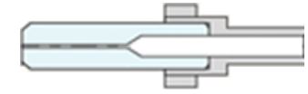
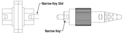
Modern fiber-optic connectors use a protruding ferrule to secure and precisely align the fiber. Figure 1 shows a schematic cross-section of a typical connector ferrule, illustrating how the tapered inner section helps self-center the fiber during the gluing and curing process.
Fiber-optic connector technology originated in the telecom industry, with common types including LC, ST, SC, FC, and SMA. While many options exist, fiber-coupled laser diodes primarily use two designs: the FC (Ferrule Connector) and the SMA905 connector. SC and ST connectors are occasionally used but are closely related to the FC design and are treated here as variants of the FC family.
SMA905 Connectors for High-Power Multimode Applications
Design and Mechanical Characteristics
Although considered obsolete in telecom, the SMA905 remains the most common connector for high-power and large-core fiber-coupled lasers. The SMA905 features a stainless-steel metal ferrule and threaded screw cap. Its inner diameter can be drilled to accommodate cladding diameters from 125 µm to over 1000 µm.
Coupling Method and Alignment Limitations
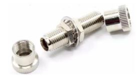
SMA905 connectors are not designed for physical contact between fibers. They mate via a simple threaded hollow tube (Figure 3). This non-contact design simplifies construction but introduces alignment uncertainty due to the lack of a keying mechanism and the relatively loose ferrule tolerances.
For a 125 µm cladding fiber, the feedthrough diameter is typically specified as 126 -0/+4 µm. This can result in core offsets up to ~10 µm. For a 105 µm core fiber, this misalignment can cause up to 20% coupling loss — note: this represents a worst-case scenario assuming maximum misalignment.
|
|
 |
Best Use Cases
- High-power large-core multimode fibers (core >200 µm recommended)
- Free-space to fiber bulkhead coupling
- Applications where core alignment precision is less critical (e.g., machine vision illumination)
Pros & Cons of SMA905
- Pros: Simple, robust, supports very large core fibers, easy to manufacture
- Cons: Poor precision, high misalignment risk, unsuitable for single-mode or small-core fibers
FC, SC, and ST Connectors for Precision Applications
Superior Tolerances and Alignment Key
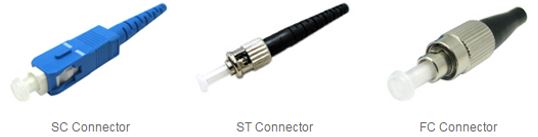
FC, SC, and ST connectors all use a 2.5 mm diameter ferrule (typically ceramic, though metal and plastic versions exist). Designed originally for single-mode fibers, they offer much tighter tolerances than SMA905. For a 125 µm cladding fiber, the feedthrough diameter is typically 126 -0/+1 µm — four times tighter than SMA905.
FC connectors include an alignment key to eliminate rotational misalignment. SC and ST use snap-in and bayonet mechanisms, respectively.
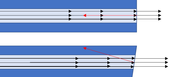
Back-Reflection Reduction
Physical contact between ferrules reduces back reflections. Angle-polished connectors (APC) further minimize reflections by reflecting stray light outside the fiber core.
Note on Polishing Process
The angle polishing process makes the fiber more challenging to manufacture because it requires great precision and control of the ends of the fiber. The asymmetric shape of the connector also increases the risk of damage at the tip of the connector if the two APC fibers are not appropriately inserted together. Despite the increase in cost and complexity, the protection that this design affords makes it a must for coupling single-mode laser diodes. Since SC, ST, and FC connectors all utilize the same type of ferrule they can each be produced in either APC or PC configurations. Therefore, it is crucial when specifying a connector for a fibercoupled laser that one denotes both the connector style and the ferrule polish, for example FC/PC versus FC/APC.
How to Choose the Right Connector
- High-power, large-core multimode (>200 µm) → SMA905
- Single-mode or small-core multimode (≤105 µm) → FC/APC
- Multimode with moderate core sizes (105–200 µm) → FC/PC or FC/UPC
- Free-space to fiber bulkhead → SMA905 is often preferred
Summary and Recommendations
Most fiber-coupled laser diodes use either SMA905 or FC-style connectors. Choose SMA905 for high-power, large-core multimode applications and bulkhead coupling. Choose FC (with appropriate polish) for single-mode or smaller-core multimode applications where alignment precision and low back-reflection are important.
About RPMC Lasers – Exclusive Distributor for LDX Optronics
For over 30 years, RPMC Lasers has been a leading laser distributor in North America. We are an OEM supplier working with the technology leading laser manufacturers from the US and Europe. RPMC supports the Industrial, Medical, Military, and Scientific markets. RPMC offers diode lasers, laser modules, solid-state lasers and amplifiers, ultra-short pulse lasers, microchip lasers, and fiber lasers and amplifiers. Also, we provide a wide range of custom solid-state lasers and laser diode subsystems.
Have questions?