
 BUY NOW
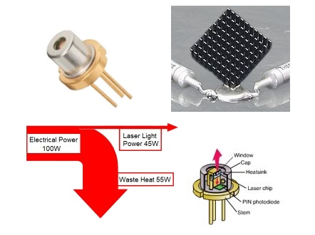
What actually affects laser diode lifetime, and which reliability factors can the OEM or system designer control?
Ask, “How long will a laser diode last?” and the technically correct response is: under what conditions?
Laser diode lifetime is not one fixed number that follows the device into every system. Reliability depends partly on how the semiconductor and package were designed and manufactured, but it also depends on how the diode is mounted, cooled, driven, protected, and integrated into the optical system.
That distinction matters for OEMs and system designers. A diode can meet the wavelength and optical-power requirement and still be a poor production choice if the package, thermal path, electrical drive, optical feedback, or operating environment pushes it into unfavorable conditions.
Looking for detailed mounting and heatsinking guidance? See our companion white paper, How to Improve Laser Diode Lifetime: Advice and Precautions on Mounting, for package-specific handling, mounting, cooling, ESD, and installation guidance.
What Determines Laser Diode Lifetime?
It helps to separate the factors that are largely built into the diode from the factors the OEM or integrator can still control.
| Primarily Controlled by the Diode Manufacturer | Primarily Controlled by the OEM / System Designer |
|---|---|
|
|
This article focuses primarily on the second column: the decisions that can extend or reduce useful life after the diode has been selected. We will still discuss device-level degradation mechanisms where they help explain why temperature, current, optical feedback, and environment matter.
What Does “Laser Diode Lifetime” Actually Mean?
A laser diode usually does not reach a predetermined number of operating hours and simply switch off. Depending on the device and failure mechanism, performance may degrade gradually over time, or the diode may experience a sudden failure.
Gradual degradation can show up as declining optical output, increasing threshold current, changing efficiency, or another performance shift that eventually takes the device outside the requirements of the system. Other mechanisms can produce much more abrupt damage, including electrical overstress or catastrophic optical damage at the laser facet.
This is why a quoted lifetime should never be separated from the conditions under which it was established. Manufacturers may characterize reliability using expected lifetime, mean time to failure (MTTF), accelerated aging tests, or other statistical methods, but the result is tied to factors such as operating temperature, drive current, optical output, duty cycle, and the criteria used to define failure.
Do not compare laser diode lifetime numbers without comparing the test conditions. A lifetime figure measured or extrapolated at one case temperature, current, or optical output does not automatically describe how that diode will behave under a different operating point in your system.
That makes lifetime less of a single datasheet specification and more of a reliability question: Will this diode continue to meet the required optical performance for the intended operating life under the actual conditions of the application?
Temperature & the Thermal Path
For many laser-diode systems, thermal management is one of the first places to look when lifetime matters. A laser diode converts only part of its electrical input into optical output. The remaining energy must ultimately leave the device as heat.
That heat has to travel from the semiconductor junction through the die attach, package, mounting interface, heatsink, and eventually into the surrounding cooling system. Every part of that path adds thermal resistance. If heat cannot move away efficiently, the junction temperature rises – even if the temperature measured elsewhere on the package appears acceptable.
The temperature that matters most is not necessarily the room temperature. Ambient temperature, heatsink temperature, package temperature, thermal resistance, electrical input power, and optical output all influence the temperature experienced by the laser junction.
A useful first-order estimate of the heat that must be removed is:
Waste Heat ≈ Electrical Input Power − Optical Output Power
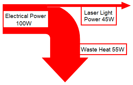
As optical power and electrical input increase, the cooling system must be capable of removing the resulting waste heat while keeping the diode within the manufacturer’s specified operating conditions. Poor contact at the package-to-heatsink interface, an undersized heatsink, inadequate airflow or coolant flow, or an unexpectedly high ambient temperature can all raise the actual operating temperature.
This is also why a laser diode’s thermal requirements should be considered early in an OEM design rather than after the optical source has already been selected. Package style, mounting surface, available heatsink area, airflow or liquid cooling, ambient temperature, and allowable system size can affect which diode is practical for the application.
Manufacturers commonly specify diode performance at a defined case or cold-plate temperature, and current diode datasheets can explicitly warn that operation above nominal conditions may reduce lifetime. The relevant temperature, limits, and cooling requirements are device-specific, so the manufacturer’s specifications should remain the controlling reference for the selected diode.
For detailed package-specific guidance on mounting surfaces, heatsinks, thermal interfaces, open packages, fiber-coupled devices, and other installation precautions, see our companion white paper: How to Improve Laser Diode Lifetime: Advice and Precautions on Mounting.
Operating Current, Duty Cycle & Electrical Stress
Laser diode lifetime is also influenced by how the device is electrically operated. The goal is not simply to run the diode at the lowest possible current. It is to operate it at a point that delivers the required optical performance while remaining within the manufacturer’s specified current, power, temperature, and operating limits.
Higher drive current generally means greater optical output, but it also increases electrical input and the heat that must be removed from the device. That makes current and temperature closely connected reliability variables rather than independent specifications.
Where the application allows it, operating with appropriate margin below maximum ratings may reduce electrical and thermal stress. The useful amount of margin, however, is device-specific. RPMC would not recommend applying a universal lifetime multiplier based only on a percentage reduction in current.
CW vs. Pulsed Operation
Duty cycle also needs context. Pulsed operation can reduce average heat generation compared with continuous-wave operation, but that does not automatically mean the diode will last longer. Peak current, pulse width, repetition rate, thermal cycling, and the manufacturer’s allowed pulsed operating conditions all matter.
If a diode will be modulated or pulsed, the operating point should therefore be evaluated using the limits specified for that device rather than assuming that a low average duty cycle makes a higher peak current acceptable.
The Driver Matters Too
Laser diodes are sensitive to electrical overstress. A suitable laser diode driver should regulate current appropriately for the device and application while protecting the diode from conditions such as turn-on or turn-off transients, unintended overcurrent, and other electrical disturbances.
Electrical integration also deserves attention outside normal operation. Electrostatic discharge, poor grounding practices, long or poorly arranged connections, and switching transients can damage a laser diode even when the intended steady-state operating current appears safe.
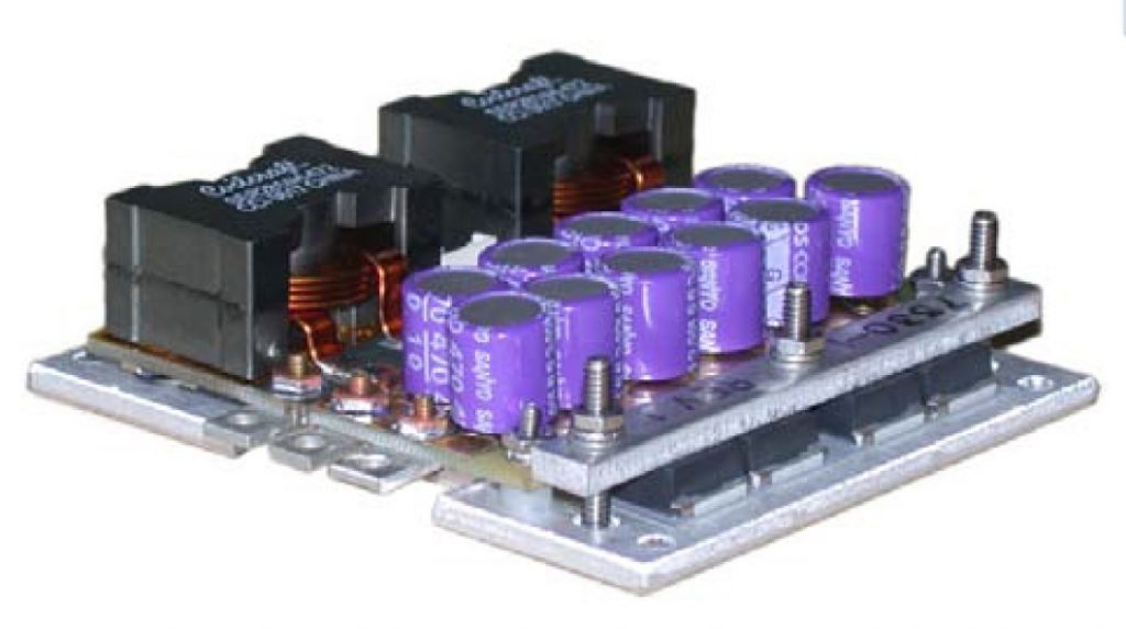
Design to the operating envelope, not just the nominal current. Current, optical output, junction temperature, duty cycle, driver behavior, and transient protection should be considered together. A diode operated within its normal current range can still experience reliability problems if another part of that operating envelope is poorly controlled.
Optical Feedback, Facet Damage & Contamination
Not every lifetime problem begins with temperature or electrical drive. The optical system itself can also place stress on a laser diode, particularly at or near the emitting facet.
Back Reflections & Optical Feedback
Light reflected back toward the laser can re-enter the diode cavity and alter its operating conditions. Depending on the device and the amount of feedback, the result can range from changes in output stability or spectral performance to permanent damage or reduced lifetime.
This is especially important when the optical path contains highly reflective targets, lenses, filters, fiber interfaces, or other surfaces that can return light toward the source. The sensitivity to optical feedback varies by laser diode, so back-reflection tolerance should not be assumed from wavelength or package style alone.
Back reflection is a system-level reliability issue. A diode can be operated at an acceptable current and temperature and still be damaged by an optical system that directs too much reflected light back into the source.
Catastrophic Optical Damage
One possible laser-diode failure mechanism is catastrophic optical damage, or COD. In edge-emitting devices, very high local optical intensity at the facet can create a positive-feedback process in which a small damaged or absorbing region heats further, absorbs more light, and rapidly develops into permanent facet damage.
COD is not the expected failure mode for every laser diode, and the threshold depends strongly on the device design, facet treatment, operating conditions, and optical intensity. For the OEM, the practical lesson is not to assign one universal COD limit, but to avoid conditions that unnecessarily increase optical or thermal stress beyond the manufacturer’s specified operating envelope.
Contamination Can Become a Reliability Problem
The laser facet and nearby optical surfaces should also be protected from contamination. Dust, oils, residues, condensation, outgassing materials, or other contaminants can absorb laser energy or interfere with the optical path. In open-package devices, where the semiconductor and facet have little environmental protection, cleanliness becomes especially important.
Fiber-coupled systems have related concerns at the fiber interfaces. Contamination on a connector or fiber end face can increase loss and local heating, and at sufficiently high optical intensity can damage the optical surface.
This is one reason package selection should reflect the real operating environment. An exposed diode that is appropriate for a controlled laboratory setup may be a poor choice for an OEM system exposed to dust, humidity, process debris, or difficult service conditions unless the system provides suitable protection.
Detailed handling, cleaning, environmental, and package-specific precautions are covered in our companion white paper, How to Improve Laser Diode Lifetime: Advice and Precautions on Mounting.
Environment, Package & Mechanical Integration
Laser diode reliability is also affected by the environment the package has to survive. A diode used on a laboratory bench may see very different conditions from one integrated into industrial equipment, a mobile platform, or a system expected to operate continuously for years.
Temperature range, humidity, dust, contamination, vibration, thermal cycling, cooling method, and available installation space can all influence the appropriate package and system design. These considerations are especially important when the diode or optical surfaces are exposed rather than enclosed in a sealed package or module.
Package selection is therefore part of the reliability decision. An open diode package can provide direct access and compact integration, but it places more responsibility on the OEM for cleanliness, handling, mounting, and environmental protection. Sealed packages or integrated modules may simplify some of those concerns, while fiber-coupled devices introduce their own requirements for connector cleanliness, fiber routing, bend radius, cooling, and mechanical protection.
Mechanical integration matters as well. The mounting scheme should provide the required thermal contact without introducing unnecessary stress into the package. In systems exposed to vibration or repeated thermal cycling, the mechanical design also needs to maintain alignment, thermal contact, electrical connections, and optical integrity over the expected operating life.
A laser diode should be selected for the system it will actually live in. Wavelength and optical power may define what the source needs to do, but package, cooling, environment, serviceability, and expected operating life help determine whether it is a practical OEM solution.
For detailed mounting, heatsinking, handling, ESD, cooling, and package-specific precautions, see How to Improve Laser Diode Lifetime: Advice and Precautions on Mounting.
What Should I Specify When Laser Diode Lifetime Matters?
You do not need to predict the exact lifetime of the diode before contacting RPMC. The more useful starting point is to define the optical requirement, operating conditions, environment, and expected service life of the system.
|
Designing for long-term laser diode reliability? RPMC can help down-select diode and package options around the required optical performance, operating conditions, thermal design, environment, and OEM integration requirements. Discuss Your Laser Diode Requirements Need detailed installation guidance? See our laser diode lifetime and mounting white paper. |