
 BUY NOW
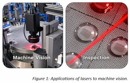
Machine vision depends on more than the camera. The illumination source helps determine what information the camera can actually detect, measure, and process.
Structured laser illumination is commonly used when a vision system needs a defined optical reference such as a point, line, grid, or other pattern. In industrial inspection and 3D measurement, the laser can make edges, height changes, surface profiles, gaps, and other geometric features easier to measure when the illumination geometry is matched to the camera and target.
The challenge becomes greater as inspection systems move beyond small parts and controlled production environments. Longer projected lines, larger fields of view, longer working distances, faster image acquisition, changing target reflectivity, and field or production conditions can all change the laser requirements.
Need to define the laser source itself? See our Lasers for Machine Vision: Selection Criteria guide for wavelength, optical power, beam quality, working distance, timing, packaging, and other source-selection considerations.
How Structured Laser Illumination Creates a 3D Measurement
One of the most common structured-illumination techniques in machine vision is laser triangulation. A laser line is projected onto the target while a camera observes that line from a known angle. Changes in the target height or surface profile cause the apparent position of the laser line to shift within the camera image.
Because the relative positions and viewing geometry of the laser and camera are known, the vision system can use that displacement to calculate height, profile, position, or other dimensional information. Instead of simply illuminating the object, the laser line becomes part of the measurement reference.
The same principle can be applied to anything from relatively small components on a production line to larger surfaces and more complex profiles. As the required inspection area, working distance, or measurement speed increases, however, the illumination requirements can change substantially.

Laser triangulation uses the displacement of a projected laser line, viewed from a known camera angle, to calculate surface height or profile.
What Changes as Inspection Gets Larger or Faster?
A laser source that works well for a small inspection area does not necessarily scale directly to a longer line, larger field of view, greater working distance, or faster measurement. As the inspection geometry changes, the amount and distribution of useful light reaching the camera can change substantially.
Longer lines and larger illuminated areas spread the available optical power over more of the target. If the same source power is distributed across a longer line, the optical power per unit length decreases. That can reduce the signal available to the camera, especially when the target has low reflectivity or the system must operate in the presence of significant background light.
Longer working distances change both geometry and alignment sensitivity. At a fixed fan angle, increasing the distance between the projection optics and target increases the line length. Longer distances can also make pointing stability, focus, line width, and mechanical alignment more important to the measurement.
Faster inspection reduces the time available to collect light. Higher line speeds, faster frame rates, or shorter camera exposures may require more usable optical signal during each acquisition. The relevant question is not simply whether a higher-power laser is available, but whether the system can deliver enough appropriately distributed light to the target and camera during the required exposure time.
Target and environmental conditions matter as well. Surface finish, color, reflectivity, viewing geometry, ambient illumination, contamination, and other conditions can affect the amount of useful signal returned to the detector. A source that performs well on one material or in a controlled environment may require a different wavelength, power level, or illumination geometry in another system.
The goal is not simply “more laser power.” The goal is enough usable optical signal across the required line or measurement area, at the actual working distance and camera exposure, with the beam distributed in a way the vision system can use.
These requirements also influence how the laser line or structured pattern should be generated. Different optical architectures can produce different line lengths, intensity profiles, working distances, and integration tradeoffs.
How is the Laser Line Generated
There is more than one way to create a laser line or structured illumination pattern, and the appropriate approach depends on the source beam, required geometry, working distance, optical power, uniformity, and system architecture.
Refractive Line Optics
Cylindrical lenses and other refractive optics can spread or focus the beam into a line. These approaches can be relatively simple and compact, but the resulting line width and intensity distribution depend on the input beam and optical design.
Diffractive Optics
Diffractive optical elements can create lines, grids, crosses, multiple points, and other structured patterns. Their suitability depends on the input beam characteristics, optical power, wavelength, required pattern, and the design of the element itself.
Homogenizing & Micro-Optic Approaches
Lens arrays, homogenizers, and other micro-optic designs can redistribute the beam to achieve a desired line shape or intensity profile. These approaches may be useful when the inspection system requires a longer line or more controlled power distribution across the measurement area.
Scanned Illumination
A moving or scanned beam can create an effective line or measurement pattern over time. This can provide flexibility in some systems, but scan rate, motion control, synchronization, mechanical complexity, and the required measurement speed must be considered together.
The important question is not which line-generation method is universally best, but which architecture produces the required line length, width, intensity distribution, working distance, stability, and optical signal for the measurement.
Power Density, Line Uniformity & Camera Exposure
For line-based inspection, total laser power is only part of the optical requirement. The vision system ultimately depends on how much usable light reaches the target, how that light is distributed across the line, and how much signal the camera can collect during each exposure.
Power density changes as the illuminated area changes. If the same optical power is distributed across a longer or wider line, less power is available per unit area. This is one reason larger inspection areas or longer working distances may require a different source, optical design, or operating point than a small-part inspection system.
Line uniformity affects the signal presented to the camera. A line with a strong center and weaker edges may be acceptable for some measurements, while other systems benefit from a flatter intensity distribution across the useful field of view. The appropriate uniformity depends on the target, camera response, image-processing method, and acceptable variation in the measurement.
Camera exposure time also changes the optical requirement. A slower inspection system may allow the detector more time to collect light, while high-speed motion or higher frame rates can require shorter exposures. Shorter exposure times reduce the amount of light collected during each image, which may increase the required optical signal at the target.
Think of the laser, optics, target, and camera as one measurement chain. Increasing source power can help in some systems, but it cannot compensate for poor wavelength selection, unsuitable line geometry, excessive optical losses, or an illumination profile that does not provide the camera with useful information.
This becomes especially important in industrial and field inspection, where the system may need to measure a large surface, operate at significant working distance, acquire images while moving at speed, or maintain useful contrast under changing environmental conditions.
Industrial & Field Inspection Applications
Structured laser illumination is useful anywhere a vision system needs a consistent optical reference for dimensional measurement, surface profiling, alignment, or defect detection. The required source can vary substantially depending on the size of the measurement area, target speed, working distance, environment, and required resolution.
- Production-Line Inspection: Laser lines and other structured patterns can support dimensional checks, edge detection, gap measurement, alignment, and automated inspection of parts moving through a manufacturing process.
- 3D Profiling & Surface Measurement: Laser triangulation can be used to reconstruct height and profile information for components, assemblies, surfaces, and other features where shape or dimensional variation matters.
- Large-Part & Large-Area Measurement: Longer projected lines and greater working distances can support inspection of larger components or surfaces, but they also increase the importance of optical power distribution, line uniformity, focus, and pointing stability.
- Rail & Transportation Inspection: Structured illumination can help measure rail geometry, alignment, gaps, wear, surface condition, and other features while the inspection platform moves along the track or roadway.
- Road & Surface Inspection: Laser-line systems can support 3D measurement of cracks, potholes, texture, deformation, and other surface features when paired with the appropriate camera, geometry, and image-processing system.
- Rugged or Field-Deployed Inspection: Systems operating outside controlled factory environments may also need to account for temperature variation, vibration, contamination, ambient light, mechanical stability, and long-term alignment.
These applications do not all require the same laser architecture. A compact direct-output source may work well in one machine, while another system may benefit from a higher-power source, fiber delivery, different beam-shaping optics, or a configuration designed around environmental and integration constraints.
Direct vs. Fiber-Coupled Laser Delivery
How the laser is delivered to the inspection point can be just as important as the source specifications. Both direct/free-space and fiber-coupled architectures can work well for machine vision, but they solve different integration problems.
Direct / Free-Space Source
A direct-output laser can provide a relatively simple optical path and compact installation when the source can be mounted near the illumination point. Package size, beam position, thermal management, mounting stability, and access to the beam-shaping optics become important parts of the machine design.
Fiber-Coupled Source
Fiber delivery can allow the laser source and its thermal load to be located away from the inspection point while routing the optical output to a smaller delivery head. Fiber core size, numerical aperture, coupling, output optics, bend radius, connectorization, and the required line-generation geometry should be considered as part of the complete optical system.
Neither architecture is inherently better for machine vision. The right choice depends on available space, optical power, beam requirements, thermal design, routing, service access, working distance, and how the illumination optics must be integrated into the machine or inspection platform.
What Should I Specify for an Industrial Machine-Vision Laser?
You do not need every specification finalized before contacting RPMC. Start with the inspection or measurement requirements you already know, and we can help narrow the source and illumination options.
|
Need help matching the laser and illumination architecture to your inspection system? RPMC can help down-select standard, configurable, or custom laser-source options around the camera, target, working distance, measurement speed, and integration requirements. Discuss Your Machine-Vision Requirements Still defining the source? See our Lasers for Machine Vision: Selection Criteria guide. |