
 SHIPS TODAY
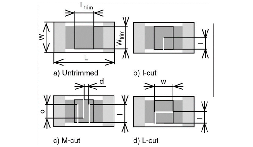
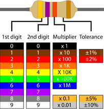
During any manufacturing process, there is some statistical variation in the finished product. Resistor manufacturing is no different, and for many years traditional bulk and chip resistors have been tested and sorted into bins and labeled based upon these tolerances. Board mount chip resistors are also similarly tolerance using a numerical code instead of a color code, but the end result is the same. However, this is not feasible in larger format thick-film or thin-film intergraded circuits which require initial calibration, such as operational amplifiers, voltage dividers, and oscillators, where the resistors are one small detail in a much more complex architecture. In this case, precise control over the resistance values is required in order for the overall circuit to properly function. This requires that these thin and thick film resistors be actively “tuned” during the test and calibration process, by using a laser to trim a small amount of material resulting in slight increases in the resentence.
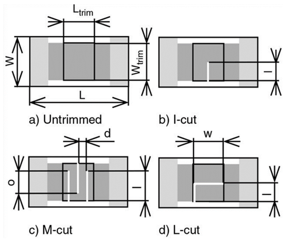
In this blog post, we are going to examine the process of laser trimming of resistors and explore the relevant laser properties needed to effectively produce the desired results. If your goal is to simply trim the resistor for a predetermined resistance value, this process can be done passively using only a resistance bridge for measurement purposes, but the majority of modern systems require active trimming where key parameters of the devices are monitored during the trimming process. One example where active trimming would be used is in an oscillator where the resistance determines the frequency band for which amplification will occur. In either process, there are several different types of cuts which are used for trimming such as the “I-cut,” “L-cut,” and “M-cut.” While a full analysis of the pros and cons of each of these cuts is beyond the scope of this blog post, it is import to note that in order to make this process economically feasible there is a constant trade-off between speed and accuracy.
This constant drive for increased speed and accuracy of the cutting process is the primary driver behind the laser specification in this application. First and foremost, the laser needs to have a perfect TEM00 beam profile since these cuts are typically on the order of 25 microns in width. Second, the laser needs to provide sufficient pulse energy to completely ablate the film in one pulse. A good rule of thumb for this is that the pulse energy must be a minimum of 0.5 mJ, otherwise, this process will be slowed down by requiring multiple passes over the same area and could potentially damage the substrate material. Lastly, the laser should have a sufficiently large pulse repetition rate as to not be the limiting speed factor in the system. Since integrated circuit manufacturing is a high-volume low margin business the faster the prats can be moved through the process the more economically viable the process is.
Here at RPMC, we offer the JenLas nanosecond fiber laser series from Jenoptik in Germany. The JenLas is available in 4 different configurations, pulse repletion rates up to 200 kHz, pulse energy up to 1 mJ, and a M2 <1.8. This makes this laser ideally suited for high-speed resistor trimming applications. Additionally, the JenLas comes with back reflection protection, an on-axis guide laser, and both software and hardware control interfacing making the system easy to integrate into modern industrial process systems.
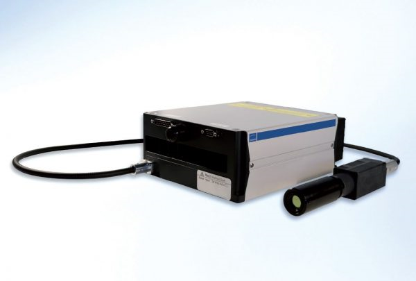
For detailed technical specifications on the JenLas series of nanosecond pulsed fiber lasers from JenOptik click here or talk to one of our laser experts today by emailing us at [email protected].